A properly selected current transducer for an application can easily give 25+ years of service. By acknowledging the details behind the data sheet, better performing applications and more robust designs are possible.
Erik Lange, Marketing & Applications Engineer | LEM USA, Inc
Current measurement is an integral part of power electronics. Current transducers supply this measurement with different technologies available. The most common technology used is the Closed Loop Hall Effect or Closed Loop Flux Gate. The Closed Loop technology offers many specific benefits needed by power electronics designers. However, there are some details not often known that can make an application exceptional or may result in failure. Below are some of the characteristics that should be considered.
Current transducers are passive devices in the concept that they do not actively influence the current being measured, yet they do require power to operate. Typical supply requirements are in the sub 30mA range regardless of supply voltage. Most transducers require a bipolar supply (+/-15V being typical). Unipolar supply transducers are becoming more available. Closed Loop devices have additional current draw requirements for their secondary currents.
Two Main Transducer Characteristics
Current transducers (not to be confused with current transformers) can measure DC and AC currents. DC measurement requires current transducers. This is one of the two characteristics that set transducers apart from other forms of current measurement. A pure AC current could be measured by a common current transformer. But if the current being measured has periods of time without di/dt, a current transducer is needed.
Galvanic Isolation is the second characteristic that drives the selection of current transducer as the solution to a current measurement application. The current transducer’s primary circuit and secondary circuit are electrically isolated from each other. This allows for a high primary potential (480V) while the secondary is a lower control voltage (+/-15V or +5V). The Galvanic Isolation is achieved through magnetics. The primary current generates a magnetic field which is concentrated by a magnetic circuit. A magnetic measuring device measures the B field and outputs the intensity in some form (voltage or threshold current). The intensity information is converted into a voltage or current output that is proportional to the primary current.
The original current transducer developed is the Open Loop Hall Effect. This transducer consists of three parts: a magnetic circuit, a Hall Cell and an amplifier. The output is a voltage proportional to the primary current.
Closed Loop Hall Effect
The next advance in transducer technology is the Closed Loop Hall Effect. The Closed Loop takes the Open Loop concept and adds a secondary winding to the output. This secondary winding is wrapped around the magnetic circuit in a way that the secondary current creates a magnetic field in opposition to that created by the primary current. This creates a relatively flux-less core. The benefits of the Closed Loop are a virtual lack of eddy currents and higher bandwidth. The output can be modeled as a current source with a current proportional to the primary current in a ratio determined by the secondary winding count. The fact that the gain is determined by the secondary windings count makes it virtually immune to gain change over temperature. A Closed Loop transducer data sheet will not indicate a temperature effect on gain characteristic. There is no effect on gain from temperature in a Closed Loop device. The current output is a benefit as it is less susceptible to noise sources within the application. The output current of a Closed Loop is typically driven through a ‘burden’ resistor. The current passing thorough the resistor creates a voltage drop that can be measured by an analog to digital IC or comparator IC.
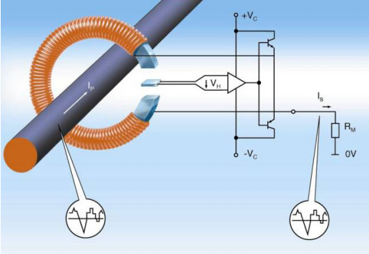
Fig 1. Closed Loop
Closed Loop Flux Gate
The Closed Loop Flux Gate replaces the Hall Cell with a Flux Gate detector. The Flux Gate is a piece of magnetic material inserted into a gap in the magnetic circuit. The Flux Gate core has a winding around it that is stimulated by a square wave voltage. The current induced is measured and when it reaches a certain threshold, the square wave cycle changes. The duty cycle of the square wave is proportional to the primary current. The Flux Gate technology is digital in nature and has an internal clock that can show up as noise at the clock frequency. However the noise is well above the bandwidth of the transducer. Thus the complete system consists of: magnetic circuit, Flux Gate and winding, an ASIC and a secondary winding. The burden resistor may be internal to the device which will then yield a voltage output. Otherwise, a current output would be generated. There are other Flux Gate technologies that use different excitation and detection schemes, but the overall results are similar.
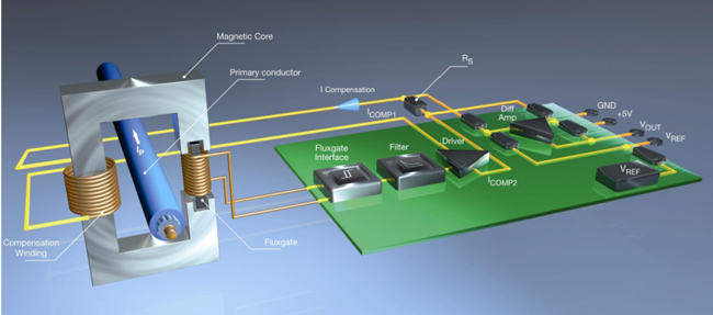
Fig 2. Flux Gate
Closed Loop transducers are designed to measure a continuous current equal to or less than the nominal current stated on the datasheet. The current being measured is typically referred to as the primary current. The output current from the secondary connection of the transducer is referred to as the secondary current. Closed Loop transducers can measure higher currents than the nominal (the measuring range), but these higher currents can only be measured for a short period of time (seconds, ms or μs).
The benefits of a Closed Loop current transducers is similar to that of a current source which includes higher noise immunity and higher accuracy.
The purpose of the current transducer is to measure current. But to what degree of uncertainty? These are not ideal devices and have an accuracy value associated with them. Oddly enough, the gain is defined by a mechanical characteristic: how accurately the secondary coil is wound by the winding machine. Linearity is defined by the material characteristics of the magnetic circuit. Offset is a function of the residual magnetism of the magnetic circuit. The gain is not impacted by temperature as previously stated. Offset, however, is impacted by temperature. The offset drift over temperature will have an impact on the application (torque ripple for instance). This is the advantage of the Flux Gate. Flux Gate transducers have lower initial offset and lower offset drift over temperature than the Hall Effect based devices.
Order of Magnitude
One significant challenge in all measuring devices is how many orders of magnitude can be measured. This is a function of accuracy. Confidence in a measurement requires a level of accuracy at the point being measured in order to be confident of the number. A ratio of 4:1 at a point should be a minimum (10:1 is better). A 100A device that is 1% accurate might measure 1A accurately, but how to know? This is where ‘reading’ and ‘rating’ come into play. Gain is always a percentage of reading, the primary current’s actual value. The linearity is a percentage of rating, with respect to the nominal rated current of the transducer. Offset is also a percentage of rating. These three errors are not typically added. This would produce a potential error budget that would be unrealistic. The errors are generally squared individually, added and the square root taken. A transducer that is 1% gain error, 0.5% linearity error and 0.2% offset error is 1.14% accurate. The actual uncertainty in amps varies with the magnitude of the primary current due to the gain being interpreted in relationship to the actual amps read. A 100A transducer with the accuracy just stated above, reading 10A, would have an uncertainty of 0.55A, better than 10:1. A 100A transducer reading of 1A with the accuracies shown above would have an uncertainty of 0.54A. The 0.54A is worse than 2:1 with the 1A being measured and would not be a reliable measurement.
This is the order of magnitude challenge. Most transducers will handle measurement below their nominal rating to one order of magnitude. Two orders of magnitude is a serious challenge. Some of the better Closed Loop transducers come close to 4:1 at two orders of magnitude. More so if the initial offset is zeroed out on power up and the offset drift over temperature is minimized (Flux Gate). Please remember that the measured accuracy does not end with the transducer. The accuracy and drift of the burden resistor come into play (1% vs 0.1%) and the accuracy of the A-to-D converter also. Checking the system using a 2% accurate splitcore Open Loop oscilloscope probe will not give valid comparisons to a 0.5% accurate current transducer.
Derating
Transducers will have current, temperature and bandwidth ratings on their respective data sheet. All three cannot be simultaneously exercised to the limit. The internal amplifiers of the transducer have limits. Voltage drops and therefore power is shared between the amplifier, secondary winding and the burden resistor. A smaller burden resistor pushes more power to the amplifier, resulting in higher amplifier temperatures. Having too large a burden results in clipping. High ambient temperatures combined with high measured currents and a smaller burden result in higher power dissipated in the transducer amplifier. These factors must be taken into account during design. Derating charts are typically available to quantify the interaction between these three variables. Closed Loop transducers do not perfectly compensate the flux in the core. As amplitude and frequency increase there is more uncompensated flux in the core. This will lead to eddy currents and core heating. Therefore the need for derating.
Aperture and Primary Conductor
Placement of the primary conductor within the aperture of the transducer will have an impact on accuracy. Centering of the conductor and sizing the transducer or conductor to fill as much of the aperture as possible improves accuracy. Please keep in mind that placing the primary conductor up against the edge of the aperture can produce localized saturation at higher currents depending on the transducer manufacturer. Not all magnetic cores are created equal. Some manufacturers over-engineer their cores and some design to the exact current with no room for error.
Datasheet
All manufacturers provide data sheets for their current transducer products. However, there is no data sheet ‘standard’. There are similarities and many differences. Some data sheets have the measuring range given, but no nominal value. Running continuously at the maximum limit defined as the measuring range may have negative consequences. Accuracy may be a combination of gain, linearity and offset errors for one manufacturer and only gain for another. Some have tighter winding accuracies during manufacture; +/-3 windings, versus others, +/-10. The resulting gain errors will be different. Bandwidth can be given at the +/-1dB or +/-3dB point.
Summary
A properly selected current transducer for an application can easily give 25+ years of service. By acknowledging the details behind the data sheet, better performing applications and more robust designs are possible. Characteristics such as accuracy, temperature effects, derating and burden resistor selection all have performance impact. This leads to the need for a knowledgeable partner as a transducer supplier.

About LEM
LEM is a market leader in providing innovative and high quality solutions for measuring electrical parameters. Its core products – current and voltage transducers - are used in a broad range of applications in industrial, traction, energy and automotive markets. LEM’s strategy is to exploit the intrinsic strengths of its core business, and develop opportunities in new markets with new applications. Together with production plants in Geneva (Switzerland), Machida (Japan), Beijing, (China) and our regional sales offices, LEM offers a seamless worldwide service. LEM has been listed on the SIX Swiss Exchange since 1986. The company’s ticker symbol is LEHN.
The content & opinions in this article are the author’s and do not necessarily represent the views of RoboticsTomorrow
Comments (0)
This post does not have any comments. Be the first to leave a comment below.
Featured Product

