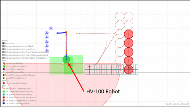
For the Harvest Automation engineering team to get an accurate view of what the robot is seeing, we've constructed a tool that we call Mindprobe which collects all the sensor data, interprets it and displays this in a graphical form.
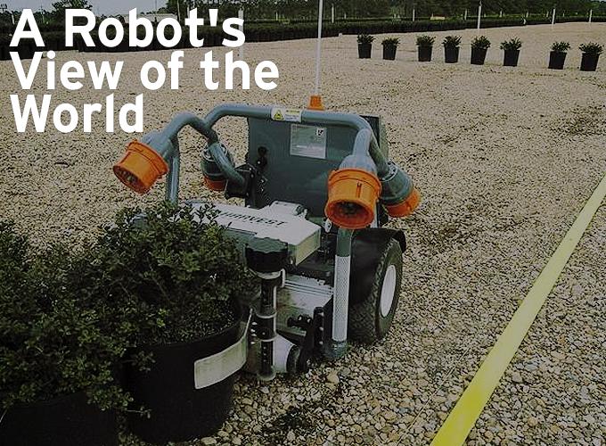
Contributed by | Harvest Automation
The Harvest Automation HV-100 Robots use a variety of sensors to "see" the world and understand their place in it. Accelerometers, gyroscopes and motor encoders each impart some notion of the robot's surroundings, but it's two other sensors - a laser range finder and boundary sensors - that are effectively the robot's eyes, which we rely on for the most important information.
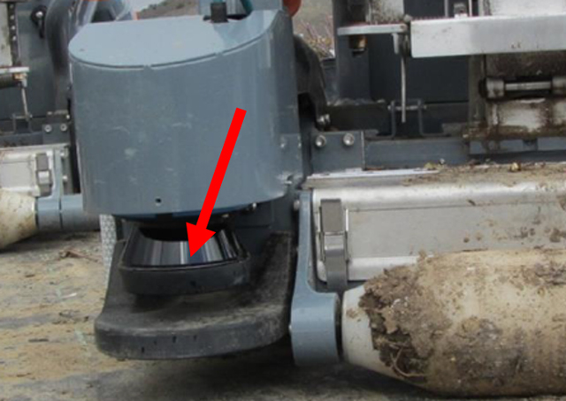
The laser rangefinder is the main vision sensor used by the HV-100 robots. This sensor is used to locate plants that need to be moved and to identify the pattern and location to move a plant into. It's also used to see obstacles in the robot's path, and identify team-mates. The laser rangefinder sees the world as a 2-D plane about 5 inches off the ground. The laser rangefinder is the shiny conical object to the left of the front roller, when looking at the robot from the front. The rangefinder emits a beam of IR parallel to the ground and sweeps that beam in a circle, while simultaneously looking at reflected signals that bounce off the surroundings. From this information it can construct a 2-D map of it's surroundings.
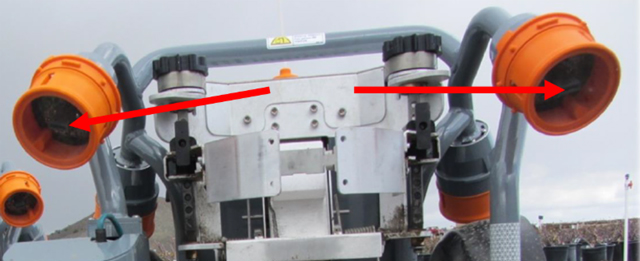
The boundary sensors are the four orange cups attached to the ends of the tube frame. Boundary sensors are used to locate and follow the yellow retro-reflective boundary tape that users deploy to mark the edge of the bed. They work by shining IR light onto the tape and looking for the reflected signal. The robot servos its path on this tape and follows it until it finds a spot to place the plant that it is carrying.
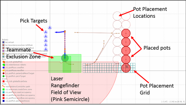
For the Harvest Automation engineering team to get an accurate view of what the robot is seeing, we've constructed a tool that we call Mindprobe which collects all the sensor data, interprets it and displays this in a graphical form as shown below:
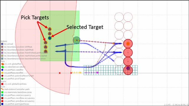
The first step in a spacing task is to select and pick a target. In the image below the robot has selected the pot denoted by the green circle with a star.
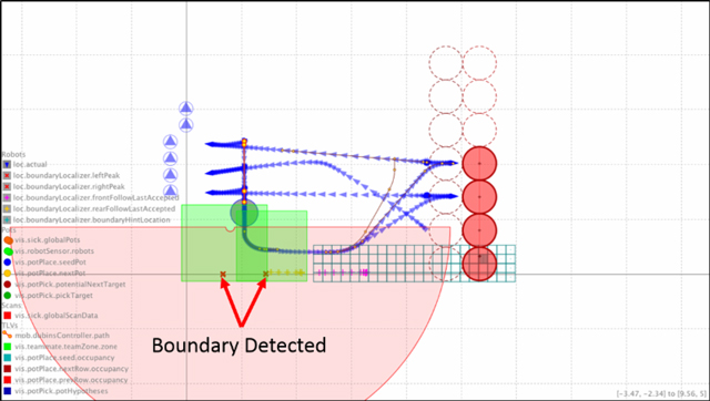
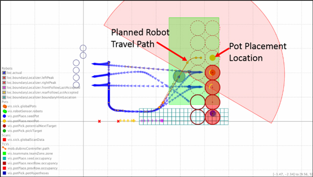
Once a pot has been picked the HV-100 turns toward the boundary tape. In the image below, the boundary is detected by the two front boundary sensors at the locations marked with bold red 'X's. Paths marked with blue arrows indicate previous circuits that the robot has taken.
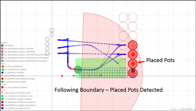
After the HV-100 has found the boundary it turns to follow the boundary using the right front and rear boundary sensors (in this example). It then begins searching for placed pots (indicated in the below image by the red circles), and empty pot placement locations (dashed red circles).
Finally the HV-100 chooses a pot placement location, plots a path to that location and deposits the pot that it is carrying. From there it turns toward the unspaced pots and repeats the entire operation.
Visit our YouTube Channel to view a video download of Mindprobe on a Harvest Automation HV-100 in action.
The content & opinions in this article are the author’s and do not necessarily represent the views of RoboticsTomorrow
Comments (0)
This post does not have any comments. Be the first to leave a comment below.
Featured Product