Machine designers are increasingly asked to build systems that take up less space, operate on less power, and run with higher performance. Thankfully motion controls are answering the call with new motors, new sensors, and new architectures.
Motion Control Goes Small
Chuck Lewin | Performance Motion Devices
Machine designers are increasingly asked to build systems that take up less space, operate on less power, and run with higher performance. Thankfully motion controls are answering the call with new motors, new sensors, and new architectures. Read on to learn about the latest developments as motion control goes small.
Introduction
It seems that every day there are announcements of smaller and smaller motors, controls, and sensors used in precision motion control. What is driving these applications is the growing demand for motion control components used in surgical, patient treatment, mobile robotics, drones, and battery-powered applications. In this article we will introduce you to recent developments in motion control technology that are letting engineers build systems that use less power, make less noise, and take up less space.
We will look first at the motors themselves to understand how they are evolving and assimilating new sensor and control techniques to boost their performance. Then we will focus on controls to show not just how and why motion control components are physically shrinking, but how new control techniques are being used to maximize motor and system performance.
Finally we will look at how the evolution of motors and controls are impacting architecture. Because it turns out that smaller and more efficient controls allow entirely new approaches to where the controls are located, how they are wired, and how these changes are having a major impact on performance, reliability, and cost.
Mini motors 101
Figure 1 shows two graphs comparing various motor types in two key performance metrics: power output to weight, and torque output to weight. For a given application usually one of these two factors are more important than the other, and in fact, they are related because power is defined as torque times spin rate.
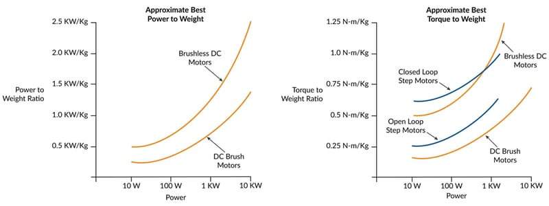
Figure 1: Comparison of Motor Types in Two Key Performance Metrics
As the graph shows, Brushless DC motors, with their ability to generate a constant torque up to a high spin rate, typically provide the highest figures of merit for power output to weight. Typical values are double the ratio of DC Brush motors. Step motors, although frequently used in portable applications, are not usually part of the power to weight conversation because their torque drops off rapidly as rotation speed increases.
If we instead want to optimize torque to weight, step motors are back on the table. Traditionally open-loop operated step motors have high holding torques, but their ability to deliver that torque over a working speed range is affected by their tendency to oscillate. Practically speaking, this means the effective torque delivered by the step motor is between 50% and 70% of the motor's rated holding torque.
There is an alternate way of operating a step motor however which largely solves this issue. A technique called closed loop servo, also called stepper servo, uses an encoder to operate the step motor as if it were a two-phase Brushless DC motor. The result is significantly higher torque over the operating range of the motor because mid-range instability, a torque killer for open loop step motors, is eliminated. More on this up and coming technique a bit later in the article.
I sense a change
An interesting aspect of the evolution of motor/actuators is how they utilize (or not utilize) sensors. As motors get smaller and smaller, and as they are implanted or strapped on to patients or used in mobile robots, it becomes harder and harder to add sensors without impacting the motor package size or the robustness of the motor/sensor combination.
So one trend affecting motors is sensorless operation - eliminating sensors and operating the motor using control techniques such as back-EMF (for Brushless DC motors) or electronic stall detection (for step motors).
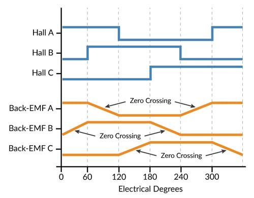
Figure 2: Back-EMF for Brushless DC Motors
There are simple and fancy ways to utilize the back-EMF of each winding of a Brushless DC motor. Figure 2 represents the most straightforward, measuring the back-EMF of a floating leg while the other two legs are being driven. The floating leg, no longer influenced by the drive output of the amplifier, contains the back-EMF voltage which can be used to determine the zero-crossing point, allowing a specific location of the commutation cycle to be determined.
Back-EMF works very well under the right circumstances but has so far not been adopted in general purpose motion applications. The first challenge is that back-EMF signals disappear as the velocity of the motor decreases. So, for all practical purposes sensorless Brushless DC applications cannot be used in positioning applications where the motor needs to be controlled around a stationary location.
In a velocity control application however sensorless drive has seen significant adoption. Although we still have the problem of not being able to sense back-EMF signals at low velocity, the controller can overcome this limitation by using a microstepping drive technique (operating the Brushless DC motor as a step motor) to bring it up to speed and then switching to back-EMF commutation once the measured back-EMF signal provides sufficient signal to noise.
When it comes to step motors, sensorless operation means more or less the opposite. Step motors can position all the way down to zero velocity but need help as the velocity increases, where they are prone to losing steps or having the motion collapse altogether. Sensorless electronic techniques can help by reducing the tendency to oscillate at certain speeds and by detecting that the rotor has stalled.
However the same "it works till it doesn't" limitation that applied for sensorless Brushless DC motors operation applies here as well. It is difficult to guarantee that electronic stall detection will work 100% reliably, so step motor applications that are really mission critical tend to use an encoder to confirm the motion.
When the going gets tough the tough get sensing
Strangely, motors of all types including very small motors are also trending in the opposite direction, upgrading their sensors to overcome the robustness limitations mentioned earlier, or adding sensors to motor types that previously did not use them.
Upgrading the sensor for robustness often means moving away from optical sensors, which are otherwise the workhorse of motor position sensing in the form of the quadrature incremental encoders. So to address the needs of harsh environment and medical applications there has been an uptick in the use of non-optical sensing solutions such as magnetic and capacitive encoders.
Shown in Figure 3, magnetic encoders can be hermetically isolated from the motor, measuring the position through a small air gap. The motor's rotor carries a magnetic encoding disk typically mounted at the very end of the motor shaft, while the electronic portion of the encoder uses either Hall sensors or magneto resistive sensing techniques to determine the rotor position. Magnetic encoders have leapt forward in resolution since their inception, and now can provide quadrature resolutions of 1,024 counts per rotation or more.
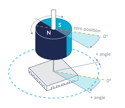
Figure 3: Magnetic Encoder Hermetically Isolated from the Motor
Capacitive encoders can also be hermetically sealed from the motor, and therefore have seen growing interest for use in harsh environment and medical applications.
Aiding the adoption of these new encoder types are improvements in the controls which use high precision A/Ds (Analog to Digital converters) and algorithmic techniques to compensate for small irregularities in the encoder's analog output signals along with fast arc-tan calculations to generate resolution-enhanced position values.
Funny, you don't act like a step motor
Step motors aren't normally operated with an encoder, but are now going through an evolution which relies on an encoder to operate the motor as a servo motor- essentially spawning the birth of a fourth motor type for positioning motion applications; after Brushless DC , DC Brush, and traditionally controlled step motors.
We will look at this technique in a bit more depth below, but the characteristics of this "new" motor type are very high acceleration rate, high torque to weight, and a reduction or elimination of the vibration issues found with normal step motors.
This new approach is driving the evolution of the step motor itself. For example, step motors used with the closed loop stepper control mode often utilize a 3.6 deg per step design rather than the traditional 1.8 deg per step configuration, and the rotors are becoming lighter to allow higher acceleration. Typical applications for the closed loop stepper include coil winding machines, textile equipment, high speed pick and place, die bonding, and others.
When the dust settles it seems that we will have two groupings of step motor designs, those designed to be traditionally controlled using full, half, or microstepping techniques without an encoder, and those designed to be controlled as a servo.
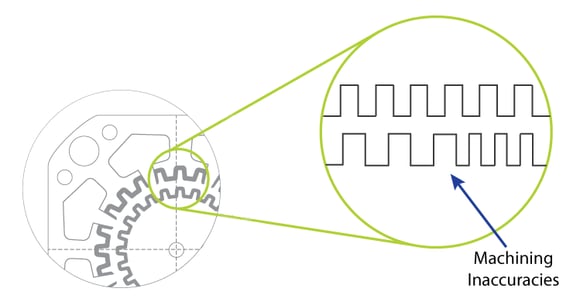
Figure 4: Step Motor Machining Inaccuracies
There is an interesting footnote to this that makes closed loop stepper particularly impactful for very small step motors.With traditionally-sized step motors such as NEMA 23 or NEMA 17 it is not all that difficult to machine the rotors and 'matching' stators consistently enough to maintain a consistent step size during motion.
As shown in the Figure 4 above, step motors have a large number of 'teeth' in the rotor, each of which should align precisely with corresponding teeth in the stator for optimum equal-step motion. As the rotor gets smaller and smaller though, the relative impact of small machining inaccuracies has a larger and larger impact on the performance of the motor.
Closed loop step motor operation, because of its ability to smooth over these underlying variations, is becoming an important technique allowing step motors to keep getting smaller and smaller without need for exotic and expensive machining techniques.
Article continued on Performance Motion Devices website here.
The content & opinions in this article are the author’s and do not necessarily represent the views of RoboticsTomorrow
Comments (0)
This post does not have any comments. Be the first to leave a comment below.
Featured Product