RASC-AL Exploration Robo-Ops Competition (i.e., Robo-Ops) is an engineering competition sponsored by NASA and organized by the National Institute of Aerospace. In this exciting competition, undergraduate and graduate students are invited to create a multi-disciplinary team to build a planetary rover prototype and demonstrate its capabilities to perform a series of competitive tasks in field tests at the NASA Johnson Space Centers Rock Yard in June 2013.
We were fortunate to be given the opportunity to show off some of the leading entries into the RASC-AL Exploration Robo-Ops Competition. Here are 5 of the design reports:
Worcester Polytechnic Institute
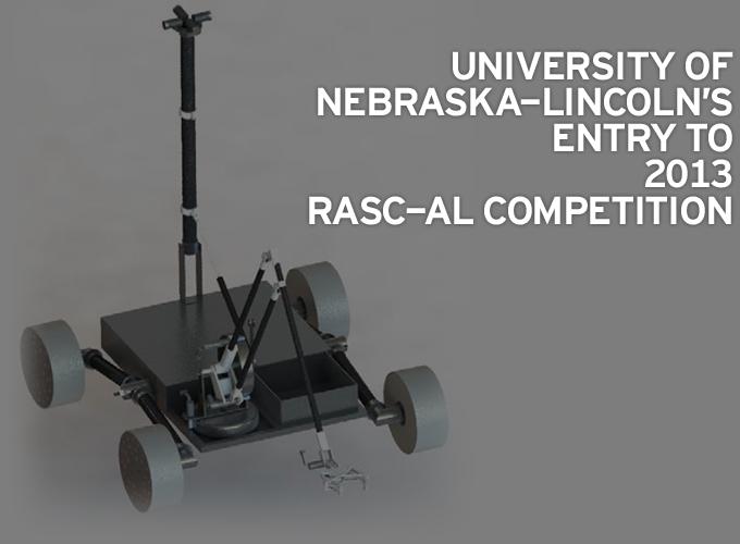
University of Nebraska-Lincoln
FAMU/FSU College of Engineering
INTRODUCTION
The Robo-Ops competition invites students to design and build a teleoperated rover prototype to traverse a planetary analog environment at NASA’s Johnson Space Center. The competition provides a set of requirements that help to restrain the designs of teams while providing some of the factors that professional NASA engineers face with every space project. The rover must not weigh more than 45kg and must fit into a 1m x 1m x 0.5m box. It may expand from that position, but it must do so on its own. It needs to be able to collect rock samples and to be able to traverse rocks up to 10 cm in diameter.
Students at the University of Nebraska–Lincoln (UNL) have formed a team of individuals with strong interdisciplinary skills in the fields of mechanical, electrical, and computer engineering to compete in this competition.
It is the unified goal of the UNL Robo-Ops team to design and build a rover that will meet the competition’s requirements. This report serves to explain the major systems of the proposed rover as well as the plan to move forward with the design when selected.
STRATEGY
The rover will begin on top of Mars Hill where it will take a quick initial scan of the area. The magnetic bearing of any visible rocks is recorded to be picked up later. Once the scan is complete, the rover moves towards an identified rock for capture. If no rocks are seen, then the rover drives around exploring the terrain. A GPS on the rover starts recording position to form a map of this particular region (Rock Yard, etc.). The driving is completed through the use of fixed forward-facing cameras. The cameras that are on the mast are constantly used to survey the surrounding area. When a rock is approached, an overlay is placed on the driving view that represents the approximate workspace of the arm. In this way, the rover is not stopped outside the useable extents of the arm. After the rover stops, the operator indicates to the program which rock is targeted. The forward facing cameras are used together to form a stereoscopic estimation for the location of the rock. Based on this information, the arm is automatically positioned above the rock. The final alignment and grasping task are completed by the operator. When the grasp is secured, the robot automatically moves the sample to the collection container and deposits it. After deposition, the arm moves to a holding position and the rover is ready to repeat the process.
MECHANICAL SYSTEMS
The platform for the rover is loosely based on the Sample Return Rover, shown in Fig. 1., from the NASA Jet Propulsion Laboratory. This rover was about the same size as our proposed rover and used a passive rocker type suspension system to allow the rover to traverse obstacles over one half its wheel diameter. Unlike the Sample Return Rover though, our rover will use a skid steering system to reduce the weight and complexity of the rover design. By building the rover from light materials we have been able to estimate a rough weight of the entire rover at 33 kg.
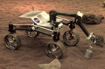
Fig. 1. Sample and Return Rover from NASA's Jet Propulsion Laboratory
Drivetrain
Wheels:
The accepted size for wheels to go over a 10 cm obstacle is one that has a diameter of at least twice that. In this way, the obstacle is always approached in a fashion that allows it to be climbed. This leads to a wheel that is at least eight inches in diameter. Sizing the wheel by this constraint is largely applicable to systems that have fixed wheels. The proposed rover has two sets of wheels, one per side, that provide a passive averaging suspension. In this way, the rover can actually climb obstacles much larger than the 10 cm.
The difficulty with the wheels is how to find a material that is light and rigid. Milling a complete wheel is far too expensive, and large pipe does not offer many advantages. Metal spinning is a great option, but the blanks that can be found are also relatively expensive. The alternative that was discovered was metal spun aluminum cooking pots. These pots are 10% the cost of metal spun blanks, but provide the same base shape. The bottom four inches of the pot will be cut off for the wheel blank.
The pot will provide the structure and the basis for driving. The outer rim of the pot will be coated with a rubber or foam layer to provide slight cushioning as well as traction on smooth rigid surfaces.
Suspension:
The overall diameter of the wheel determines the sizes of obstacles that can be surpassed. The climbing ability of the rover can be further enhanced through the use of suspension on each of the four wheels. For the rover, a differential rocker system was chosen. The two wheels on each side are joined at a central hip that can rotate relative to the body. This system passively averages the angles of the two sets of wheels (left and right) so that the rover body tilts less. This averaging also allows more wheel contact to be maintained during a climb.
There are two common methods for creating the differential system. The first was used on JPL’s most recent rover, Curiosity, and is made up of a pivoting bar across the back of the rover. This bar mechanically couples the left and right side to provide the passive averaging. The second method, and the one selected for our rover, is the use of a miter gears to form a differential system between the wheels. This construction was chosen since it provides the differential movement in a package that can be completely contained within the body.
Chassis
The frame is to be created out of two different sizes of square aluminum tubing. The main enclosure is framed in ¾” square tubing. This tubing provides ample strength and will keep the two wheel sets rigidly constrained. Brackets within this base frame will be ½” square tubing. This tubing will be used to support the electronics, arm, and camera mast. These subsystems are relatively light and can be held in place with this lighter tubing.
Further weight reduction was studied as it pertains to the drilling of through holes along the axis of the tubes. It was found that only minor weight reductions could be achieved for extensive work, so it was decided that the frame be left solid. With solid wall tubing and a thin sheet metal skin, the frame is expected to weigh approximately ten pounds. A dimensioned view of the rover in its stowed configuration is shown in Fig. 2.
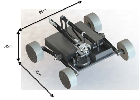
Fig. 2. Dimensioned View of Rover in Stowed Configuration
Arm
Arm:
The arm design was an area of much discussion. Simple arms are easy to build but are not flexible in their abilities. Complex arms can add unnecessary weight and expense. Based on past experience in building robotic arms, the challenge of a complex, but lightweight, arm was undertaken.
A parallel linkage base for the arm was decided on for its ability to locate three of its motors at the shoulder joint. A motor at the wrist provides a pitch angle and one on the hand actuates the grasper. This parallel system was designed to utilize the strength and weight of carbon fiber tubes. This allows an arm that weighs less than a kilogram to reach and pick up a rock four feet from its base. The entire system was sized so that it is capable of packing on top of the rover. Two cable-capstan drives will be used for the first three joints Fig. 3. This type of drive creates no backlash and has very little inertia. Even with the backlash created by the motor gearboxes, it is estimated only 0.1° will be apparent at joint outputs. Additionally, a single drum can be shared between two motors when using the arm’s parallel linkage system.
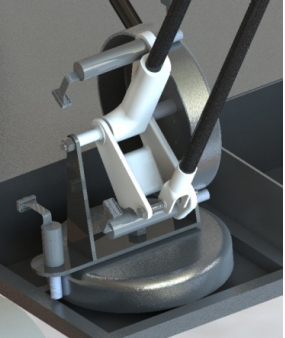
Fig. 3. Base of Arm Showing Parallel Linkage and Cable/Capston Joints.
With the parallel linkage, carbon fiber tubes, and the cablecapstan drive, this rover is capable of carrying a rigid arm with an extension length of over four feet. With this large reachable workspace shown as the green area in Fig. 4, rover placement is much less of a concern, and collection time will be reduced.
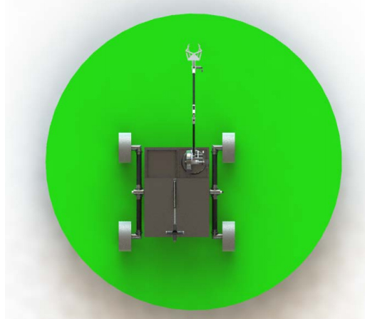
Fig. 4. Rover Shown with Arm Workspace
Grasper:
The design of a grasper leads to a myriad of options. The simple designs include buckets or claws. Bucket graspers tend to be large and difficult to precisely place, but their simplicity allows simple pickup of most rocks. Claw based graspers include two or more fingers. Two fingered graspers are enough, but with the addition of fingers, the compliance of the grasping motion is increased, along with the complexity. A two fingered grasper was prototyped. This design was shown to be able to pick up the target rocks, but the grip on the rocks was not necessarily secure. The addition of compliant foam to the finger tips provides more security as the rock deforms into the foam, increasing the contact surface and distributing the grasping force.
Alternative designs are being tested that could produce a hyper compliant multi finger grasper in a simple to build/actuate package.
A camera is planned to be mounted in the base of the palm to provide feedback on hand positioning.
Control:
With a multiple degree of freedom arm, there are a set of kinematics that describe the motion of the endpoint relative to each of the arms angles. These equations allow the use of generic control devices such as Phantom Omnis. These devices enable a lot of freedom as an interface, but since the controller is generic, controlling the arm precisely is not intuitive. To achieve an intuitive interface, a kinematic master of the arm is planned. Due to the workspace of the arm, the master will be built to half-scale. The operator will grasp the gripper end of the master and directly control the joint angles of the arm.
Camera Mast:
The environment will be surveyed through the use of a mast mounted camera system. The camera mast will be raised from its stowed position by the solenoid release of a pin holding the tension of a gas spring hooked to the mast. Traditional arrangements of a camera mast include a camera with a mechanical pan and tilt device. Creating this type of device allows the operator to drive the camera to each area of interest. This subsystem was discussed for improvements.
The inclusion of tilt was looked at first. The use of tilt was determined to be used very rarely for surveying the field. A replacement to mechanical panning is proposed. Four webcams will be included looking forward, back, left, and right. These images will be combined and sectioned on a computer on board the rover. Portions of these images will be sent to the operator based on the virtual panning angle command.
Provided enough bandwidth, the four webcam images can be stitched together to provide a panoramic view of the environment. In this situation, the operator has full visualization of the field without potentially missing a target due to incomplete panning.
ELECTRICAL SYSTEMS
The rover has three electrical systems including the motion control system, main computing system, and the auxiliary computing system. A main power bus will distribute power to each of these systems.
Motion Control System
The rover requires multiple motors to drive around and use its robotic arm. Each motor will be connected to the motion control system, which consists of off the shelf motor controllers connected to the main computing system.
Motors:
The rover consists of two separate motor systems, the drive motors and the arm motors. The motors for both systems were chosen to be Maxon brushless motors for their high power density. Many aspects must be considered when picking motors for an application, including weight, current consumption, top speed, torque, and cost. Calculations regarding all these aspects were completed to determine that the motors used to drive the rover should be 200W Maxon brushless motors. Similar calculations were performed on the requirements for the arm motors to determine that they should be 40W Maxon brushless motors. All motors will be operated at a nominal 24 V.
Motor Controllers:
Off the shelf servo drive motor controllers will be used to control the rover’s motors. The feedback systems on the motor controllers must be able to provide at least velocity control for the drive motors and position control for the arm motors. Besides meeting these requirements, the controllers must have a straightforward application programming interface (API) that has been proven in industry to work with Linux operating systems. Of the options currently being explored, digital servo drives from Elmo Motor Control and Advanced Motion Controls seem promising. These controllers can be connected to the main computing system by either USB or a CAN bus.
Computing Systems
The controls of the entire rover will run through one main onboard computing system. This system will be connected to the command computer at UNL over the internet with a 4G LTE USB modem. The onboard controlling computer will be an 8W embedded system with an Intel Atom processor, 64 GB Solid State Drive (SSD), and 4 GB RAM. This system is a very low power and efficient system that will be capable of reading sensors and controlling motors. Sensors, including an inertial measurement unit and GPS, will be connected to this computer via USB and read into the control software. If needed, a camera may be connected to compress and send an unprocessed video feed.
The semi-autonomous modes of the rover rely upon complex computer vision algorithms and will require a powerful computer system to run them. The stereo reconstruction algorithm requires the processing of two video frames concurrently to determine the depth of a point in the image. Either these two images are first encoded and sent over the 4G network to a powerful computer at UNL to be processed, or only one image is sent to UNL and the processing occurs onboard the rover. Due to the upload bandwidth (~.4Mb/s) of the 4G network, it was decided that it is better to only send one video frame over the network at one time and to do the processing onboard the rover. A potential option for the computer to do this processing is a Mini-ITX system with a 65W Intel i7-3770S processor, 16 GB RAM, and a 64GB SSD. This system should provide all the required power in a small, robust, energy efficient package. The system will be powered by a 12 VDC power supply connected to the power bus. Multiple cameras will be connected to this system to provide the images for the computer vision algorithms.
Auxiliary Computing System
There are a few components on the rover that are not easily interfaced with the previously mentioned computing systems. Examples include absolute serial encoders for the robotic arm and a solenoid to release the gas spring on the camera mast. To read and control these items an embedded microcontroller system will be used. Possible choices include an Arduino or BeagleBoard system. These systems run at a 5V TTL level, so they will be powered by the 5V line on the power bus.
Power System Architecture
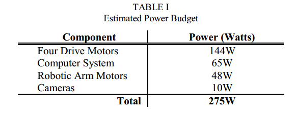
The power system must be able to supply sufficient power to the rover motors, computer system, cameras, sensors, and miscellaneous equipment. This equipment will run at three different voltages. The motors will operate at a nominal 24V which the battery packs provide. The computer system and battery management system will run at a regulated 12V and a 5V line will be added to support the auxiliary computing system. The 12V and 5V voltages will be converted from 24V with two DC-DC switching converters. The estimated power requirements of the electrical system are detailed in Table 1.
The competition requires the rover to operate for at least one hour including a possible 10 minute repair intervention. To allow for a safety factor on the power requirements, the team plans to have an operation time of two hours. This requires a battery pack with a capacity of 550 Watt-Hours (Wh). The highest voltage in the system is the 24V the motors are to run at, so to save weight the battery pack will be designed to have a nominal voltage of 24V. At 24V, the battery capacity must then be about 23 Amp-Hours (Ah), to meet the 550 Wh power requirement, including inefficiencies in the DC converters and electrical components. Due to their high-energy density, the battery packs for the rover will be custom assembled from either lithium-ion or lithium-polymer cells. The cells will be connected to a computer controlled battery management system to provide onboard monitoring and balancing of the cells. A charging port will be built into the frame of the rover to allow charging without removing the battery pack from the rover. A diagram of the power system architecture is shown in Fig. 5.
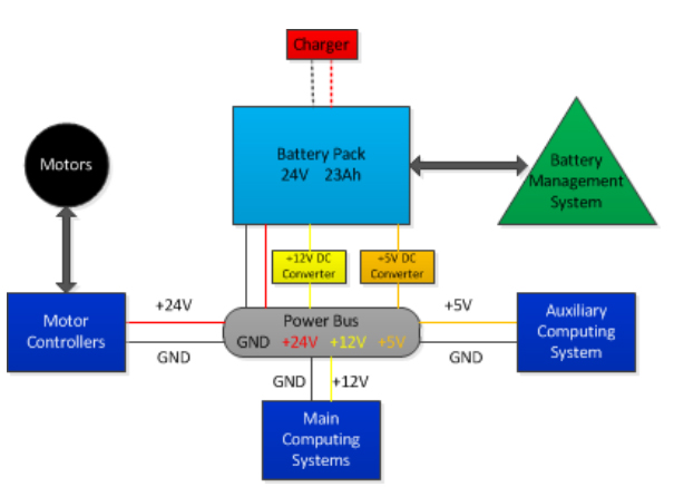
Fig. 5. Diagram of Power System Architecture
SOFTWARE AND PROGRAMMING
The software to control the rover will be based on the Robot Operating System (ROS) distributed computing architecture developed by Willow Garage. This architecture allows the code for the rover to be split up over multiple machines. This is useful because the team will be relying on information from two computers on the rover to manually control it over the internet from a command center computer at UNL. These three computer systems will have to work together to provide all the information needed to control the rover. ROS allows seamless communication between these computers.
The control of the rover will happen from the command center computer at UNL. This computer will provide a control interface to the driver in the form of a graphical user interface (GUI), a game console controller (i.e. Xbox Controller), and a kinematically matched robot arm controller. Code for reading in the controllers will be written in either C++ or Python. The GUI will consist of several displays, including telemetry data from the rover, a map with current heading of the rover, and video feeds from the cameras on the rover. The GUI will either be written in Python or Java. To help determine when a rock is in the video feed, OpenCV will be used to write a program that will pick out the unique colors of the rocks and alert the driver to them when they appear. This algorithm will be written in C++ to allow it a quick operating time.
A computer on the rover will use the control information sent from the command center to control motors and other systems on the rover. This computer will also read in sensor information from the motor drivers, inertial measurement unit, GPS, and the auxiliary microcontroller to be sent to the command center. These programs will either be written in C++ or Python.
The auxiliary microcontroller will be used to read in absolute encoders and control a solenoid. This code will be written in embedded C.
The video feedback from the rover will be processed and compressed by a separate high-powered computer on the rover dedicated to computer vision tasks. This computer will be connected to the rover’s cameras and will compress and stream the video feeds selected at the command center. These programs will be written in C++ because of the increased speed it provides compared to Python.
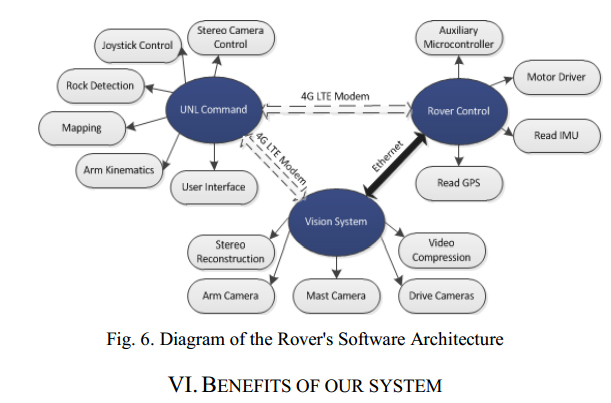
Besides using the kinematically matched robot arm controller, the arm will be able to be semi-autonomously controlled through the use of position information from a stereoscopic reconstruction algorithm. The process for this starts when the rover sends a video feed from one of the drive cameras in a stereoscopic pair of drive cameras on the rover. The command center computer will receive this video feed and display it on the GUI. When a rock is seen by the driver on the drive camera video feed, they may click on it with the mouse and the pixel number they clicked on is sent back to the vision system computer on the rover where a reconstruction algorithm determines the three-dimensional position of the rock. The rover will then, using the arms kinematics, autonomously move the arm to a calculated spot right above the rock. The user will then control the arm to pick up the rock. The software for this algorithm will be written in C++. A diagram of the ROS architecture is displayed in Fig. 6.
BENEFITS OF OUR SYSTEM
Simple skid steer
There are several main methods of steering that can be used in a rover like this. Multiple methods allow for precision steering through allowing a yaw motion on at least two of their wheels. Although this is beneficial, it was determined that the added weight and complexity of this system made this method impractical.
Stereoscopic mapping
An onboard computer is dedicated to vision acquisition and recognition. The drive camera is one of a pair of fixed, forward-facing cameras. These will be used in a stereoscopic fashion to provide single frame depth information. This information will be used to automate some arm movements.
When a rock is approached and the rover stops, the operator can select the desired rock to grasp. The depth information will be used to automatically move the arm directly above the target rock. The final approach and grasping will be done manually by the operator.
Automatic rock deposition
After a rock has been grasped, the operator can start a sequence that will automatically deposit the rock in the storage container and then move the arm to a default position that is within the rover envelope and has the palm camera facing the front.
Camera overlays
Our rover will use high definition cameras to scan it environment. Combining human filtering and selected color filtering will allow colored rocks to be easier to pick out. When approaching a rock, an informational overlay will inform the driver of the expected reachable workspace for the arm. In this way there is no question of how close the rover needs to get.
Alternate Arm Usage
The length of the arm and the inclusion of a webcam on the palm make it a very versatile tool. The arm can inspect all parts of the rover with its camera. This ability will provide hazard camera-type feedback when necessary. When driving, the arm can be raised to five feet as a secondary camera mast. This provides a higher vantage point and an alternate view for driving and surveying.
GPS Mapping
The movement of the rover within a particular region may not proceed with any sort of efficiency since it is largely a random search. Keeping track of a rough path based on GPS readings will allow the operator to check that the entire environment has been searched. This information will also be invaluable in quickly returning to the transport zone after collecting the rocks.
Innovative Weight and Cost Reduction
The restriction on weight of the rover is very central to the goals of NASA and its missions. While the maximum is 45 kg, the goal for this design was set at less than 30 kg. To maintain that weight, subsystems were designed specifically for maintaining sound mechanical practices while creating components that are lightweight and require little to no machining. The use of standard size material will limit the amount of machining. Also thinking outside the constraint of standard materials has led to the use of cooking pots for the wheels and polyurethane expanding foam for reinforcement.
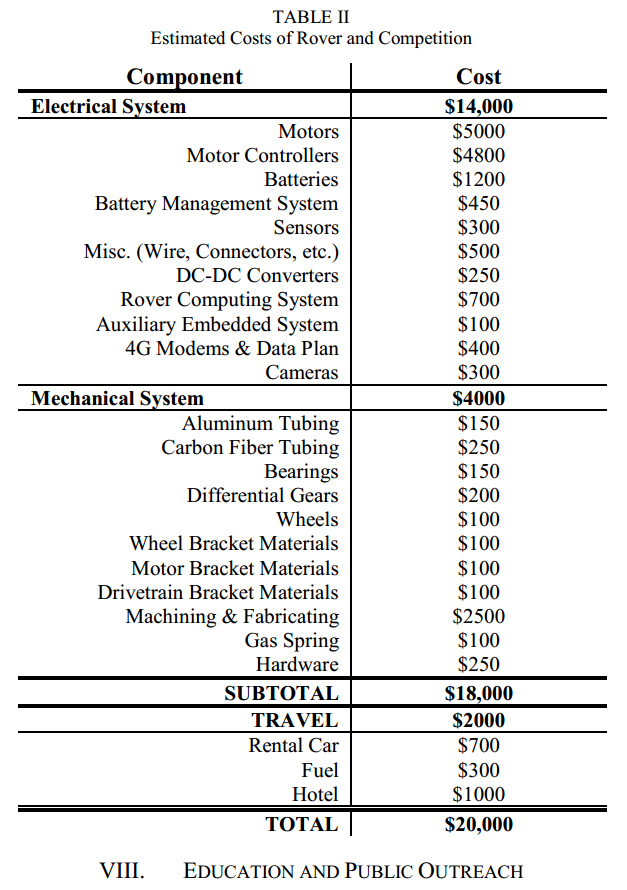
ESTIMATED BUDGET
A conservative cost estimate of the rover came to $20,000. With the competition funding level of $10,000, the team has found outside funding for the remaining cost. Dependent on our acceptance into the competition, the NASA Nebraska Space Grant Consortium will provide $5000 in additional funding. The University of Nebraska – Lincoln’s Mechanical and Materials Department has also provided an additional $2500 in funding. The remaining $2500 in funding has been found from local companies as in kind donations of machining, fabrication, and materials. A cost breakdown is provided in Table 2.
EDUCATION AND PUBLIC OUTREACH
To achieve the education and public outreach goals of the competition, the team will partner with the College of Engineering’s Communications office. The duty of this office is to help advertise and promote the student activities in the College. This includes setting up webpages, social media sites, and writing press articles. With their help the team will be able to meet the education and public outreach goals of the competition.
We have made arrangements to exhibit the rover at the US Nationals Robotics Tournament in Omaha, Nebraska in early March. This event brings 500-700 students, grades 5-12, as well as 600-700 spectators together from all over the United States who are interested in robotics. This is a great event to exhibit at since the rover is a reminder that aerospace applications are great avenues for continuation of robotics and its related fields. The use of this rover will help to further inspire this diverse group of students to stay in STEM fields.
Connections have also been made with local, middle and high school science teachers who have agreed to have us demonstrate the rover during their classes. Further demonstrations will be made during Astronomy Weekend at the University’s Museum.
TIMELINE
A preliminary timeline for the project is broken into five subcategories including, the mechanical, electrical, software, outreach, and competition requirements. The timeline of these activities is displayed in Fig. 7.
TEAM
All team members have gained a diverse skillset while performing academic research in the Advanced Surgical Technologies Lab at the University of Nebraska-Lincoln. Each brings a unique perspective and set of skills that makes them beneficial to the team as a whole.
Joe Bartels is graduate student experienced in electrical systems and programming. He is the team leader, and will specialize in the electrical and programming side of the rover. He has experience at the NASA Jet Propulsion Laboratory, in the Mobility and Robotic Systems group.
Tom Frederick has a background in computer vision techniques and the use of ROS. He has industrial experience at Lockheed Martin Space Systems. He will lead the mechanical design and ROS implementation. He is also a graduate student at UNL.
Eric Markvicka has experience in embedded control and control theory as a graduate research assistant. He contributes to the team experience in machining and robotic control. He has gained outside experience at Johnson Space Center, Honeybee Robotics, and the NASA Jet Propulsion Laboratory.
Kearney Lackasis also a graduate student and will lead the design and build process of the rover’s arm. This work will rely on his experiences gained through other aerospace projects, including AIAA’s Design-Build-Fly competition.
The team also has two undergraduates, Walter Bircher and Mark Reichenbach. Both have experience in mechanical and electrical design of precision equipment. They will contribute in both of these areas and gain experience in programming.
RESOURCES
The creation of the rover is an intensive process that requires much testing and creating. For this reason, having facilities available for this process is crucial to the projects successful completion. The team has direct access to basic tools (wrenches, drill press, bench grinder, Dremel, etc.) as well as some small machining tools like a lathe and mill. The team has made contact with local machine shops for the completion of more complicated parts. Part of a successful project is one that is efficient in terms of budget, so the team’s access to a low power laser cutter and a 3D printer will greatly increase effectiveness and efficiency by being able to create cheap prototypes.
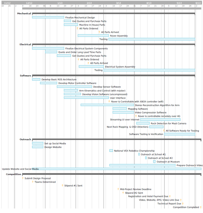
Fig. 7. Preliminary timeline for development of rover and notable competition dates
The content & opinions in this article are the author’s and do not necessarily represent the views of RoboticsTomorrow
Featured Product

