RASC-AL Exploration Robo-Ops Competition (i.e., Robo-Ops) is an engineering competition sponsored by NASA and organized by the National Institute of Aerospace. In this exciting competition, undergraduate and graduate students are invited to create a multi-disciplinary team to build a planetary rover prototype and demonstrate its capabilities to perform a series of competitive tasks in field tests at the NASA Johnson Space Centers Rock Yard in June 2013.

| Florida Agricultural & Mechanical University / Florida State University College of Engineering
We were fortunate to be given the opportunity to show off some of the leading entries into the RASC-AL Exploration Robo-Ops Competition. Here are 5 of the design reports:
Worcester Polytechnic Institute
University of Nebraska-Lincoln
FAMU/FSU College of Engineering
Student Team
Ricardo Asencio, Matthew Wilson, Myles Bean, Daniel Bucken, Parker Harwood, and Jason Rhodan.
Faculty Advisor
Dr. Jonathan Clark, PhD and Dr. Michael Frank, PhD
Abstract
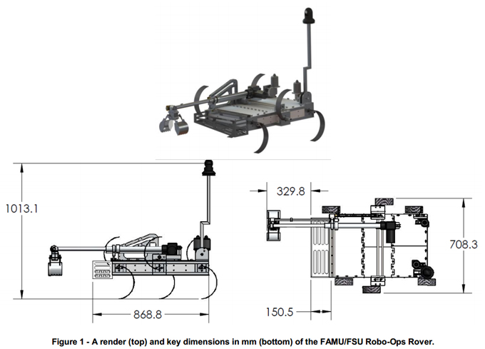
This document describes the FAMU/FSU College of Engineering’s proposed rover design for the 2013 RASC-AL RoboOps competition. The team consists of 6 undergraduate engineering students all with an interest in space exploration and a strong will to compete in this year’s competition. Guidance and working facilities will be provided to the team by their main advisor, Dr. Jonathan Clark, and the STRIDe Lab, which operates under his direction.
A hexapedal locomotion platform forms the basis for the proposed rover, and grants the rover several key features which we believe will make it successful in completing the tasks of this year’s competition. The rover also features a low degree of freedom Sample Extraction Module (SEM) designed specifically for the legged platform, an on-board Field Programmable Gate Array to consolidate logic operations (pulse-width modulation and decoding of motor signals), and a strategy for wireless control of the rover, which minimizes on-board computing requirements.
Team Leads and Facilities
Daniel Bucken, Mechanical Systems Lead – Daniel Bucken is a senior at Florida State University pursuing his BS in Mechanical Engineering. Over the past year he has been employed by the Center for Intelligent Systems, Controls and Robotics (CISCOR) as a research assistant. His work has focused on the design of robotic systems and the design of components for implementation of controls on existing platforms.
Ricardo Asencio, Electrical and Computing Systems Lead – Ricardo is a senior at Florida State University and is completing his degree in Computer Engineering. He recently completed a year-long internship with Intel Corporation in Folsom, California and plans to return for full-time work after graduation. At Intel, Ricardo had various roles but was primarily focused on system validation of modern application-specific IC's while running a complete software stack in a pre/post silicon environment. His interests include autonomous robotic systems and artificial intelligence.
STRIDe Lab, Working Facilities – Scansorial and Terrestrial Robotics and Integrated Design Lab was founded in 2007 by its director, team advisor Dr. Jonathan Clark, with the aim of developing robotic platforms which can challenge the agility and versatility of animals and insects. STRIDe Lab has worked extensively on the design and control of legged platforms and is well equipped for the task of developing a legged rover. The lab boasts several tools to aid in the manufacture of a rover including a laser cutter, composite material construction tools, extensive analysis and testing devices, and a capable machine shop available next door at the FAMU/FSU College of Engineering.
Rover Performance Summary
Functional Overview
Locomotion
The rover’s drive system must allow it to quickly navigate a multitude of terrains, including steep inclines, large rocks, and sand. This system must also not consume too much power as to allow for at least one hour of rover operation.
The proposed design will implement six individually-actuated compliant legs for movement. The performance of this configuration on extreme terrains has been demonstrated by the RHex robot and by Hexcavator, a robot successfully developed at the FAMU/FSU College of Engineering for the 2012 NASA Lunabotics competition. The hexapedal platform was also chosen for its uniqueness to the Robo-Ops competition and to take advantage of the expertise of the project advisor, Dr. Jonathan Clark, who has extensive experience with the design and control of legged-robots.
The legs are 25 cm in diameter and will be constructed out of carbon fiber to provide adequate strength and the proper stiffness with the guidance and facilities of the STRIDe lab, where substantial research on the design of compliant legs for hexapedal robots has taken place. Each leg will be driven by an independently controlled Maxon RE-50 DC-motor attached to a GP-52 Maxon gearhead, which will implement a variable rotational speed algorithm during general movement of the rover. This algorithm is known as the Buehler clock and will be discussed further in the programming section of this proposal.
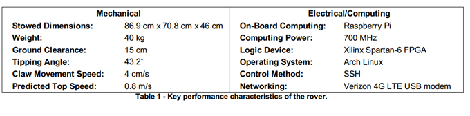
The hexapedal design is expected to perform favorably at the terrain of the JSC Rock Yard. The rover is designed to straddle objects up to 15 cm tall and sustain a tilt angle of 43.2˚ before tipping, allowing the rover to navigate large obstacles with ease. Sand presents a challenge for wheeled rover designs, as seen with the fate of the Mars Exploration Rover Spirit, the rover’s legged design grants it higher mobility in loose terrains. For example, Hexcavator navigated the fine “lunar regolith” of the 2012 Lunabotics competition with ease.
Sample Extraction
Our examination of the effectiveness of past years’ sample extraction designs suggested that the quickest extraction times were achieved by teams with either low degree of freedom manipulators or very sophisticated control schemes; ease of control was thus determined to be the primary design consideration for the robotic arm.
The proposed arm design takes advantage of the fact that the legged locomotion platform results in a non-planar rover. The vertical mobility generally found in robotic arms was removed from the arm itself since this degree of freedom may be obtained via the legs of the rover. The arm employs a simple and reliable lead screw setup for motion along the width of the rover, and a long-stroke linear actuator to move the end effector along the length of the rover. Planar motion of the end effector in both directions will occur at speeds up to 4 cm/s. The range of motion in both directions is 30 cm, resulting in a 900 cm2 operating area for the end effector.
The end effector is a hybrid pincer-scoop design. It utilizes two concave surfaces moved through pinching motion to capture the sample. This configuration combines the speed of scoop-style claws with the precision of a pincer. The scoops are toothed to enhance grip when used as a pincer and to lower the required force for the penetration of soil. The scoops also include clear rear surfaces to enhance visibility of an arm-mounted camera during positioning of the end effector. Each half of the pincer-scoop is actuated by a servo-driven fourbar mechanism. The resulting motion allows for grasping of objects up to 14 cm in diameter. The scoop-region has enough volume to enclose a spherical object 11 cm in diameter. This will allow our gripper to capture a rock within the size range specified in the design requirements.
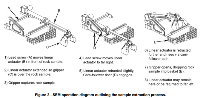
The planar arm design requires special consideration with respect to sample storage as the container must be designed to allow access to the end effector while still fully constraining the samples. A passively controlled vertical degree of freedom was added in this design via a cam-follower system to allow the end effector to rise above the storage container and release the sample, as illustrated in Figure 2.
For the majority of sample extractions during the competition, the rover will simply lie down on the ground and the end effector will operate in the ground plane, which will allow for accurate and fast sample extraction. For samples not in the ground plane shared by the rover, leg positions will be adjusted to orient the end effector’s operating plane to contain the sample.
Electrical/Computing Systems
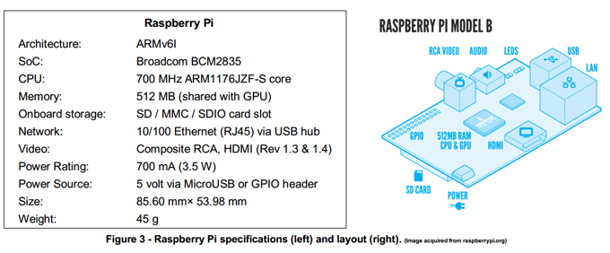
In order to minimize the required power consumption, a widely popular yet small ARM computer platform known as the Raspberry Pi will be used, which draws only 3.5 W of power. The Raspberry Pi is ultra-low-cost ($35), Linux-based, commercially available computer. The Raspberry Pi is at the center of our electrical system and will provide the foundation for the communication and control of the rover.
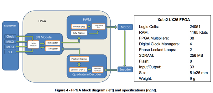
Interfacing the Raspberry Pi with a Field Programmable Gate Array (FPGA) will allow the team to develop the logic circuits needed to count the motor positions from the encoders. The selected FPGA board was a Xula2-LX25 made by Xess (Cost: $119). The Xula2 contains a Xilinx Spartan-6 FPGA and has a power consumption of approximately 2 ½ W which suits the low power profile of the design. The logic circuits that will be implemented in the FPGA are decoders for counting motor positions and pulse width modulation (PWM) for motor driving, seen in Figure 4. The communication protocol used to communicate with the FPGA and the Raspberry Pi will be the Serial Peripheral Interface (SPI) as it is available on the Raspberry Pi pin-out. The decoders will simply count the quadrature encoded signal from the motor encoders and store the values in a register which can then be read by the Raspberry Pi. The PWMs will provide a square wave that drives the motors at the appropriate speed by altering the duty cycle. The duty cycle is set inside a register which will be written to by the Raspberry Pi.
Control and Programming
The Operating System selected for the Raspberry Pi is Arch Linux ARM, which is a light Linux distribution with no Graphical User Interface and only the necessary drivers and processes are loaded at boot. This allows our user programs to use more CPU time as the OS scheduler has fewer processes which it must distribute CPU resources to. The General Compiler Compilation (GCC) and Vim (terminal text editor) were installed to create our development environment. The entire algorithm will be written in C. Figure 5 illustrates how the locomotion algorithm works and is described below.
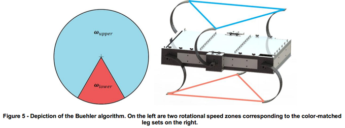
In order to provide a walking motion the locomotion algorithm used is a Buehler clock. The Buehler clock has two phases. When a triplet of legs is in the blue phase (above) the angular velocity ωupper is approximately five times faster than the velocity in the red phase ωlower. The triplets connected by the blue and red lines in the diagram above should ideally be in the same position at any instance. However, small errors are unavoidable since it is possible for legs to be traversing different terrains simultaneously. This causes the leg rotational velocity to differ even if the same duty cycle is provided to drive both motors. For example, walking over a rock and traversing sand require different torques from each motor to achieve the same rotational velocity. The control algorithm used to correct this scenario is a Proportional Derivative (PD) algorithm which regulates the rotational velocity by increasing or decreasing the torque of each leg until the leg position matches the ideal position as calculated by the algorithm. When any motor is out of position the algorithm makes a torque correction proportional to how many positions it is behind or ahead of the ideal Buehler Clock. This allows every pair of leg to respond dynamically to the terrain it is currently traversing.
Communications
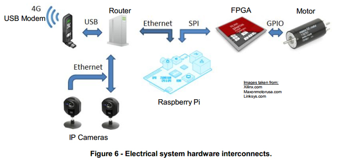
The communication hardware will mainly consist of the Verizon Wireless 4G LTE USB Modem 551L and the CradlePoint MBR1200B Mobile Broadband Router. The router has USB ports available for a wireless broadband modem connection. This modem-router configuration will allow multiple devices to connect via Ethernet to the router and send information over the wireless broadband network. The components that will require network access are the IP (Internet Protocol) cameras for video transfer and the Raspberry Pi for SSH (Secure Shell) access. A server will be set up, on campus, to receive the video feed from the cameras and control SSH access to the Raspberry Pi on the rover.
The main vision component will be an overhead Internet Protocol (IP) camera that will sit atop the camera mast and have the ability to pan and tilt. More importantly, IP cameras are designed to handle video processing and compression and send the video over a network for remote viewing without the aid of a computer. A second IP camera will mount to the Sample Extraction Module to ensure an optimal viewing angle for the operator. The consequences of the time delay that are expected will be partially mitigated by making the rover semi-autonomous in its movements. Rather than having the operator directly control the rover’s movements instantaneously; the operator will give the rover a command to walk a certain amount of steps; this will prevent the rover from stopping suddenly and toppling over. The arm will be controlled by the operator directly and will be subject to manual correction.
The SSH server and client are readily available on many Linux distributions and are a simple solution to remotely controlling the onboard computer. However, most wireless broadband carriers do not allow incoming SSH connections, but do allow outgoing SSH connections. A script was written that connects the Raspberry Pi to a local port on the campus server automatically at boot. This allows the server to then reverse-SSH into the Raspberry Pi and control the bash shell remotely. The operator can then access all of the scripts and programs written for control, calibration of the legs and error handling.
The Serial Peripheral Interface is a four wire interconnect that is used to communicate between discrete circuit components. The SPI protocol transmits information in bytes and is full Duplex, that is it receives and transmits a byte over the bus concurrently. The four communication signals are the bus clock (SCK), the select line (SSEL), MOSI (Master Output Slave Input), and MISO (Master Input Slave Output). When the select line is low the SPI slave reads a bit over the MOSI line while concurrently driving the MISO line at each and every rising edge of the bus clock as shown below.
Educational and Public Outreach Plan
The team currently maintains a Facebook page, a website, a YouTube channel, and an Instagram account to fulfill the electronic portion of the educational and public outreach (E/PO) requirements. The website is a primary hub for project documents and reports. It also contains information about all team members, sponsors, and an overview of the project itself. Most photos and videos of progress made will be posted on the team’s Facebook page. Important photos and videos will also be featured on the team’s website. The YouTube channel is used to feature all videos of progress and to chronicle important project milestones and events. The Instagram account is used to provide impromptu picture-updates on team activity.
The team has future plans to participate in public outreach events at the Challenger Learning Center, the K-12 outreach facility of the Florida A&M University - Florida State University College of Engineering. The Challenger Learning Center has a theme of space exploration, and hosts family-friendly space-oriented events year-round. There is also planned an outreach event at a local middle school to engage students with the theme of robotic planetary exploration, using the team’s rover as a set piece. Last year’s Lunabotics team visited Swift Creek Middle School in Tallahassee, FL for a portion of their community outreach. Our current team and the school have agreed to continue this partnership to peak the children’s interest in engineering and space exploration. We also plan to attend preview sessions for those looking to continue their education at our university. In doing so, we hope to inspire incoming students who are unsure of their planned field of study to enter the field of engineering.
Current Project Status
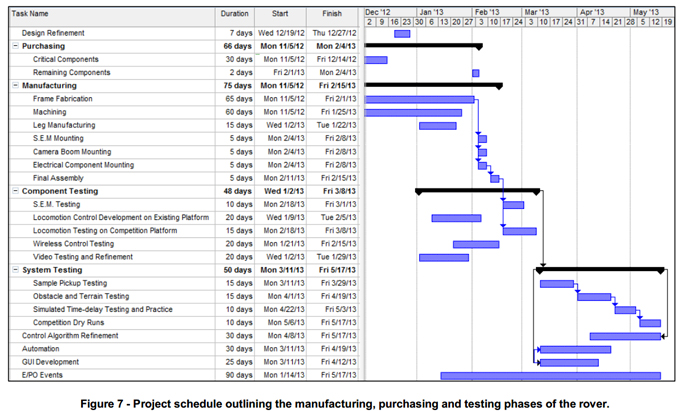
Currently, the full design of the rover has been completed, including all major electronic and mechanical components and mounting hardware. Development of the decoder and pulse width modulation logic on the FPGA board is under way and nearly complete; the team has been able to drive a motor using a Raspberry Pi and FPGA board. Wireless connectivity and control of the Raspberry Pi has been established over 3G and the team has been able to stream a webcam video over this connection. The team has also practiced forming carbon fiber legs on a small scale so that new legs can be constructed with minimum impact to schedule.
The major components and raw materials for the body and arm have been ordered. The square aluminum tubing for the frame of the rover has been cut and is scheduled to be welded by January. The various guides and parts for the SEM are undergoing CNC machining currently. Once these components are completed, they will be combined with the linear actuator that has already been received. Then, testing can begin.
The content & opinions in this article are the author’s and do not necessarily represent the views of RoboticsTomorrow
Comments (0)
This post does not have any comments. Be the first to leave a comment below.
Featured Product