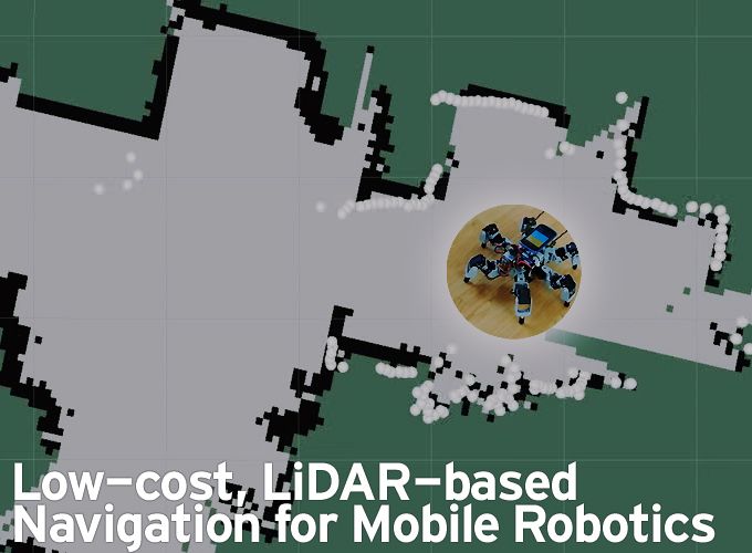
Using the ROS Navigation suite from the Open Source Robotics Foundation (OSRF), we highlight a solution employing the Rhoeby Dynamics R2D LiDAR, a low-cost LiDAR device
Contributed by | Rhoeby Dynamics
Introduction
Rapid growth in the market for mobile robotics is leading to increasing demands for low cost solutions to robotics navigation. Hardware that's traditionally used for this function is quite expensive and often over-specified for the given application. This situation has given rise to a new class of LiDAR devices, which are purpose-built, and aimed at drastically reducing the cost of entry into navigation-capable robotics systems.
This article delves into the subject of mobile robotics navigation based on the Robot Operating System (also known as ROS, see http://ros.org). Using the ROS Navigation suite from the Open Source Robotics Foundation (OSRF), we highlight a solution employing the Rhoeby Dynamics R2D LiDAR, a low-cost LiDAR device (see http://rhoeby.com).
Solutions to the problem of mobile robotics navigation typically comprise several hardware and software components, including:
- LiDAR
- localization
- mapping
- path planning
- obstacle detection and avoidance
The above components when brought together realize the navigation system, and some video demonstrations of LiDAR-based navigation in operation can be found here: http://rhoeby.com/video
In order to understand what is going on in the videos, we first cover some basic terminology:
LiDAR: stands for Light Detection And Ranging, and is similar to radar, but uses light instead of radio waves.
Localization: is the process of determining where the robot is located, relative to objects in it's environment.
Mapping: is the process of building maps based on data acquired from one or more sensors.
Path planning: is the process of determining a path for the robot to follow, in order to reach a 'goal'. A goal is just where you want the robot to go.
Dynamic obstacle detection: is the process of detecting objects in the environment that were not present during the mapping process, but are now nonetheless present.
Avoidance: is the process of path planning around dynamically occurring objects. The rest of this article will make use of these terms, and also highlight details from the above videos, to provide a framework for exploring the topic of navigation.
The LiDAR
One of the first things to understand is the operation of the LiDAR device itself. This device plays a central role in the navigation process: it's used to gather information about the objects surrounding the robot (walls, doors, etc). In the below picture 'Basic scanning in ROS', we see two things: the robot, as represented by the red circle, and the "range data" as represented by the white dots. This range data represents the basic information produced by the LiDAR device.
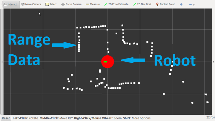
Fig 1 - Basic scanning in ROS
Internally, the LiDAR device is composed of a range measurement sensor that repeatedly transmits a pulse of light. This pulse of light hits a target (wall, person, cardboard box, etc), then bounces off and returns to the range measurement sensor. By measuring how long it takes for the light to travel out and return back, the sensor can determine the distance to the object. Additionally, the range measurement sensor is mounted on a spinning platform that allows the device to take these range measurements at many points around a 360 degree sweep. As the range measurement sensor is rotated, range readings are taken rapidly (up to ~1000 samples per second), and this yields a two dimensional view of the entire surroundings of the robot.
Mapping
As can be seen in the above picture, a sweep of the 360 degrees view and the taking of many range samples yields a crude "map". But this map is usually far from complete. So the second part of the process is to take many of these 360 degree scans and assemble them into a more complete map. As the robot begins to move around in it's environment, it is able to estimate where is it relative to the current and previously scanned data (the process known as "localization"), and then take new scans and add them into the map. The process of performing localization and mapping together is commonly referred to as "Simultaneous Localization And Mapping", or just simply SLAM!
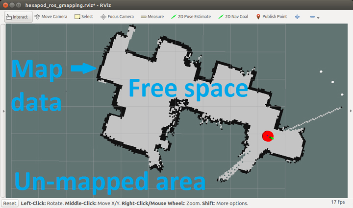
Fig. 2 - A map built using the R2D LiDAR sensor
The picture above 'A map built using the R2D LiDAR sensor' shows just such a map built using the SLAM process. Furthermore, the video 'Rhoeby Hexapod ROS-based map building' shows the full process of a map being built.
Shown below is an early stage map building task in progress. Initially, the mapping function has very limited data to start working with: it can only derive an incomplete and simple map.
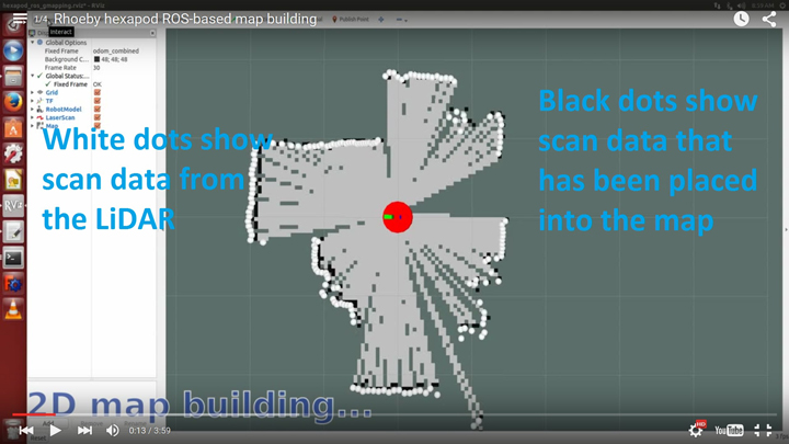
Fig. 3 – Early-stage map building
The white dots represent the scan data coming from the LiDAR and the black dots represent data that has been taken from the LiDAR and placed into the robots map. Dark gray/green areas are areas that are unknown to the robot, whereas the light gray areas are clear space. As the robot moves around, more data is gathered from the LiDAR and this is added to the map until a complete picture is built up of the robots surroundings.
Navigation
Once the map is built, the robot can then proceed to the the third and final part of the process, which is the navigation and obstacle avoidance. This is comprised of path planning, detection of new objects that are not part of the map, and updates to the path plan to avoid these obstacles. This is where the preceding elements of LiDAR, SLAM, path planning, and obstacle avoidance are all brought together.
In the picture below, we see the navigation 'goal' being set. The user clicks a location on the map where they would like to robot to go to, and the navigation software displays a large green arrow to show this goal.
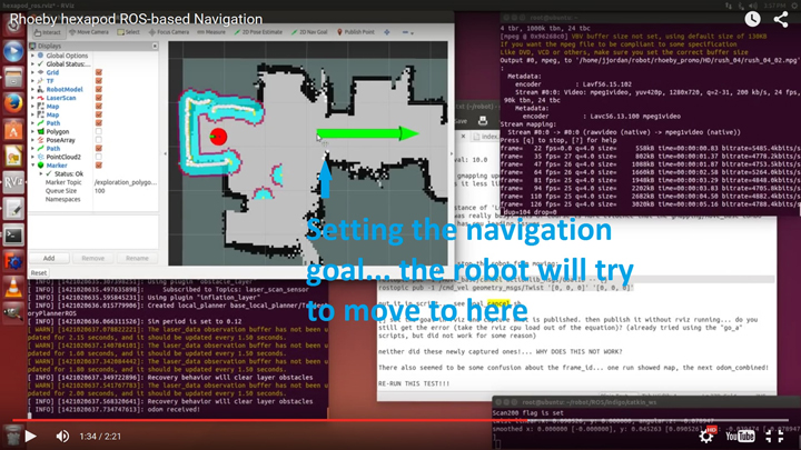
Fig. 4 – Setting the goal
In addition to showing the goal, the picture also shows:
- the mapped data: the black areas
- the scan data from the LiDAR: the white dots
- the robot current position: the red circle
- obstacle inflation: the turquoise/purple areas
All of the above, with the exception of obstacle inflation have been discussed already. So let us turn to the subject of obstacle inflation. As we know, the purpose of navigation is to travel from our current location to another 'goal' location. In doing so, we seek to avoid any obstacles. These obstacles include the walls, etc that are known to the robot from it's map building operations, and also any other new obstacles that may have appeared since the map was built. In deriving a path to the goal, the robot must avoid obstacles and allow a safe distance around them. To this end, the purpose of obstacle inflation is to make obstacles appear larger than they are, and with a safety margin, to help ensure the robot does not collide with them. So the areas of turquoise are areas where the robot should avoid, they are the danger areas where collision could occur.
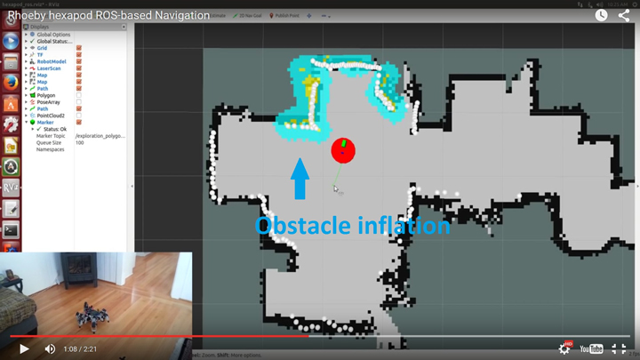
Fig. 5 – Obstacle inflation
As the robot navigates towards a goal, it maintains an area around itself where it performs obstacle inflation, and seeks to keep its path outside of those areas. Here we can see a path the robot planned to move across the room (green line):
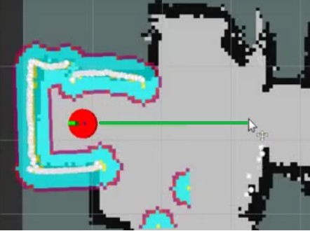
Fig. 6 – The planned path
After some time navigating towards the goal, we introduce a new obstacle (a cardboard box) and this causes the robot to have to make a new plan to reach the goal. In the next picture, we see how the new path is planned to go around the new obstacle (green line bends around the box which has appeared in the map as an inflated obstacle):
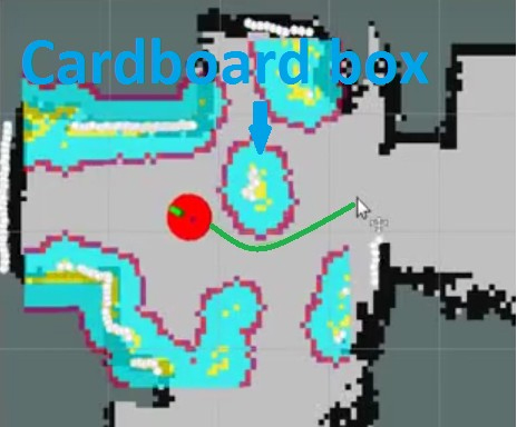
Fig. 7 – The revised path
Using these techniques of mapping, obstacle inflation and path planning, the robot is able to move towards its goal and dynamically avoid obstacles, even as those obstacles move into and out of it's currently intended path.
This article has provided a brief overview of LiDAR-based mobile robotics navigation. For much more information, please visit our website (http://rhoeby.com).
The R2D LiDAR
The Rhoeby Dynamics R2D LiDAR is the smallest, lightest, lowest-cost device on the market today. Much more detail can be found here: http://rhoeby.com/products
It's proven capable of performing mapping, navigation and dynamic obstacle avoidance in the indoor setting, and comes complete with its open-source Robot Operating System (ROS) driver for rapid integration into any robotics platform.
About Rhoeby Dynamics
Rhoeby Dynamics provides simple to use, low-cost solutions for advanced robotics navigation. They integrate robotic SLAM, navigation hardware, and software tools for state-of-the-art robots.
The content & opinions in this article are the author’s and do not necessarily represent the views of RoboticsTomorrow
Featured Product