When determining which system is right for your application, it can be difficult to visualize the impact of IMU selection on total system performance. Our goal in this paper is to show how the quality of the IMU affects the end-use system via several real-world tests.
 Benefits of a Tactical Grade IMU in Low-cost GNSS/INS Systems
Nathan Miller, David Robbins, Jonathan Bessette | Parker LORD – MicroStrain Sensing Products
There are a wide range of low-cost, MEMS-based GNSS/INS (Inertial Navigation Systems) on the market today and selecting one to meet your requirements can be an overwhelming task. The performance of the GNSS-side of a GNSS/INS is generally well understood. Less understood is the IMU performance characteristics and their effects on overall system accuracy. Although still important when GNSS is available, IMU performance is critical during GNSS outages, which are easily encountered due to obstruction and/or interference of the weak GNSS signals. When determining which system is right for your application, it can be difficult to visualize the impact of IMU selection on total system performance. Our goal in this paper is to show how the quality of the IMU affects the end-use system via several real-world tests.
IMUs used in low-cost systems are classified as being one of the following grades: consumer, industrial, or tactical. Typically, cost scales as a function of the quality of the gyroscopes used by the IMU. Recent cost reductions in MEMS gyro technology have essentially made consumer grade systems obsolete, leaving industrial or tactical grade as a decision-point for new designs. The demarcation of tactical vs. industrial grade can be hard to pin down, but a generally acceptable definition is an IMU with gyroscope In-Run Bias Stability (IRBS) of less than 5 deg/hr is tactical grade; whereas, a higher IRBS is industrial grade. For completeness, consumer grade gyros will typically have IRBS of 30 deg/hr or more.
Gyro in-run bias stability is calculated via the Allan variance method described in IEEE-STD-952-1997 and represents the random variation of the gyro bias over time. The reason this parameter is so vital is turn-on bias is typically estimated and largely removed at device power on, but the in-run bias variation continuously affects the device during runtime, and thus, limits its performance. During GNSS outages, this variation is integrated, causing error in the estimated orientation. This erroneous orientation is then used to transform the body-fixed accelerations to the global frame, which are integrated to update velocity and integrated again to update position. Through this effect, it is clear that any error in estimated orientation can have a dramatic effect on the accuracy of the estimated position.

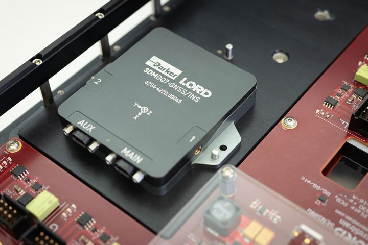
In order to show the real-world effects of IMU grade on system performance, we have conducted a series of 4 tests using two of our most popular GNSS/INS systems: the 3DMGQ7 and the 3DMGX5. The GQ7 is our latest GNSS/INS with RTK-level position accuracies of ~2cm and a tactical-grade IMU with <2.0 deg/hr in-run gyro bias stability. The GX5 is our previous generation product with single-point GNSS positioning accuracies of 1.5m and an industrial-grade IMU with 8 deg/hr in-run bias stability. The following tests were conducted:
-
Industry-standard Allan variance test
-
Stationary gyro integration test
-
Real-world GQ7 data compared to a post-processed simulation where real-world GX5 IMU data replaced the GQ7 IMU data during an induced GNSS outage
-
Real-world, head-to-head comparison of GX5 and GQ7 during an induced GNSS outage
Test 1 - Allan variance
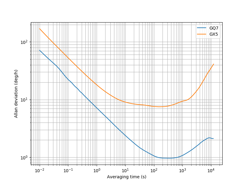
As previously mentioned, Allan variance testing for gyros is described in IEEE-STD-952-1997. Our tests are conducted on an extremely heavy granite block that is mechanically isolated from building vibrations. The IMU test units are powered on and allowed to thermally stabilize over the course of two hours in ambient conditions; then, inertial data is collected for a 12-hour period. Allan deviation (square root of the Allan variance) plots for two sensors, one 3DMGX5 and one 3DMGQ7, are shown in figure 1 below. In-run bias stability for each device can be inferred from this plot, and corresponds to the minimum Allan deviation of the curve. As can be seen in the GX5 plot, this happens at ~7.5 deg/hr with a correlation time (x-axis value) of ~175 seconds. For the GQ7, this occurs at ~0.9 deg/hr with a correlation time of ~300 seconds. It is clear from these results that the GQ7 can be classified as a tactical-grade IMU; whereas, the GX5 cannot.
Figure 1 – GQ7 and GX5 Gyro Allan variance.
Each curve represents an average over the three device axes.
Test 2 – Stationary gyro integration
One of the limitations of the Allan variance test is it doesn’t account for real-world conditions. This is by design, as ensuring similar testing conditions across different devices creates fairer comparisons. To address this, the next test we conducted was to determine the angular drift of the GQ7 and GX5 gyros over time when placed in a relatively benign, yet realistic, environment. To perform this test, both devices were securely fastened to a tabletop using VHB tape. The test was conducted at ambient temperatures in an average office environment and both devices were subject to building and floor vibrations. Thermal concerns were not addressed, and thermal soaking was not performed. Gyro delta theta (integrated angular rate) was collected at 100 Hz for 20 minutes from both devices and post processed using Matlab. The turn-on bias was mitigated using the average of the first 5 seconds of recorded data. This is similar to performing a gyro bias capture or estimating the gyro bias in real-time. The raw delta theta data was used instead of real-time Kalman filter attitude information to remove effects of aiding sensor measurements and filter differences between the two devices. With the turn-on bias removed, the data was integrated for each gyro axis.
Figure 2 below shows the non-ideal vibrations induced on the sensors during the test.
Figure 3 shows the drift in each gyro axis as function of time for the GQ7.
Figure 4 shows the drift in each gyro axis as a function of time for the GX5.
Figure 2– Acceleration measured by the GX5 during stationary test

Figure 3– Drift in integrated GQ7 gyro data over 20 minutes
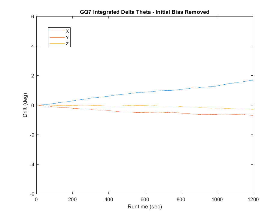
Figure 4 – Drift in integrated GX5 gyro data over 20 minutes

It is clear from these plots that lower gyro bias instability does in fact correlate to lower attitude error and the drift scales as one would expect, as the GQ7 is ~3-4 times less than the GX5. What is less apparent is why the drift seems higher over the 20-minute period than expected from the Allan variance. Here is where additional error sources, beyond in-run bias stability, come into play. As discussed, the initial bias was estimated using only the first 5 seconds of data. These estimates will be off by a small, but not zero, amount from the real turn-on bias, which was integrated over the entire collection time. Additionally, less severe, error sources also come into play, such as vibration rectification error, which has a g^2 effect. These small, non-zero errors also have a reasonable impact when integrated over long periods.
Test 3 – Real-world GQ7 data compared to a post-processed simulation using GX5 IMU data during an induced GNSS outage
Most GNSS/INS systems are not used on office desktops or lab-based granite blocks; therefore, real-world test data is valuable. The data used for this test was gathered in an instrumented Humvee (figure 5), outfitted with multiple GNSS/INS systems as well as RF attenuators for inducing GNSS outages. One of these GNSS/INS systems is a high-accuracy unit used as a reference system.
A drive in the local area was conducted and data from the reference unit, a GX5, and a GQ7 were recorded simultaneously. The reference unit and GQ7 were processing RTK corrections and an RF-attenuator was used to artificially induce GNSS outages on the GX5 and GQ7 simultaneously. In order to show the true effects a tactical grade has verses an industrial grade IMU, a post-collection simulation was conducted, replacing the GQ7 IMU data with that of the GX5. This is valid approach as both systems have accurately GPS-timestamped IMU data and the simulation has been validated previously against countless real-time datasets. Figure 6 shows the difference in Kalman filter estimated position tracks during a 30-second GNSS outage. Figure 7 shows the horizontal position error of the tactical- and industrial-grade IMU with respect to the reference unit during the 30-second outage. Comparing these two figures, you may question why the horizontal position error for the industrial-grade IMU seems higher than the distance between the two tracks on the map. It is important to note that there is an along-track (in the direction of travel) error that is difficult to discern from a 2-d plot. The filter correction for this error is evident just after the “GNSS signal recovery start” event as the filter attempts to back-track to the reacquired GNSS position measurement.
Figure 5 – Test vehicle with GQ7, GX5, and high-accuracy reference unit installed.


Figure 6 – Reported position tracks during GNSS outage – tactical vs. industrial-grade IMUs (aerial image view shown for clarity as parking lot is unmarked in map view)

Figure 7 – Horizontal position error during 30-second GNSS outage
Test 4 – Real-world, head-to-head comparison of GX5 and GQ7 during an induced GNSS outage
Post-processing and simulating data may suggest that some tricky business could have occurred (it didn’t), so let’s take a look at a head-to-head comparison. For this data, the same Humvee test system was used, collecting data in the local area with RF-attenuator-induced GNSS outages. One of the difficult things about analyzing data from a direct-comparison test is not all of the difference in performance between the two devices can be attributed to the difference in IMU performance alone. The devices under test have different GNSS sub-modules, different GNSS processing paths (loosely-coupled vs. tightly-coupled), and different Kalman filter architectures. That being said, this test is included for completeness, but it should be stated that test 3 is really the gold standard for comparing the effects of the IMU alone.
As can be seen by figure 8, the GQ7 outperforms the GX5 during the 30 second outage. It important to note that algorithmic aiding features, such as wheeled-vehicle constraint and zero-velocity updates, were turned off for this test to keep the Kalman filter estimation as similar as possible between the two units and to reduce any algorithm-induced beneficial effects. Figure 9 shows the horizontal position error of the GQ7 and GX5 with respect to the reference unit. It is clear that the GQ7 performs far superior to the GX5 during this particular maneuver.

Figure 8 - Reported position tracks during GNSS outage – GQ7 vs. GX5
Figure 9 - Horizontal position error during 30-second GNSS outage

Summary
It is clear that having a tactical grade IMU does improve navigation performance and investing in a higher performing IMU does have benefits. Recent advancements in MEMS sensor technology have allowed tactical-grade IMUs to enter the realm of low-cost GNSS/INS systems and these systems are gaining traction against their more expensive predecessors. Additionally, we have shown the progression from standardized testing all the way through to real-world vehicle testing and how one can generally expect IMU datasheet performance metrics to affect their system in the real world.
The content & opinions in this article are the author’s and do not necessarily represent the views of RoboticsTomorrow
Featured Product

