The implementation of ASIC based current transducers opens up functionality that the traditional discrete component transducers could never achieve.
Contributed by | LEM USA
Current measurement is a standard requirement in power electronics applications. Many of these applications have a DC component to the current and/or require Galvanic isolation. This drives the measurement device to a current transducer as opposed to a current transformer. A current transducer will measure AC or DC current. Depending on the accuracy and bandwidth requirements, the current transducer selection will be an Open Loop type or Closed Loop type. Higher accuracy and higher bandwidth traditionally would require a Closed Loop. An Open Loop basic accuracy is typically 1% at 25°C, whereas a Closed Loop accuracy is more likely 0.5%-0.7% at 25°C. These accuracies are a combination of gain and linearity uncertainty. Offset error is typically zeroed out on power-up and is not considered here.
Over temperature range the Open Loop and Closed Loop begin to significantly diverge with respect to the uncertainty of the measurement. At an elevated temperature of 60°C, the Closed Loop will only see offset drift of maybe 1% full scale. At the same elevated temperature of 60°C, an Open Loop may see offset and gain drift of up to 3% or more. These temperature errors are in addition to the errors defined at 25°C. Applications that get hot and/or where current measurement plays a greater role in control may require a Closed Loop solution.
The Great Leap Forward
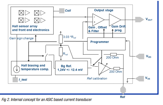
The Hall Cell is a semiconductor device. The amplifier used in both Closed Loop and Open Loop devices is also fabricated on silicon. Until approximately 10 years ago these two parts of a current transducer were manufactured separately. Current transducers were manufactured from discrete components soldered to a printed circuit board. This changed with the development of an Application Specific Integrated Circuit (ASIC) for current measurement. The Hall Cell and amplifier were placed on the same die and encapsulated together. This allows for the ASIC based current transducer. The world’s first ASIC based current transducer was the LEM LTS series Hall Cell Closed Loop transducer for printed circuit board operations.
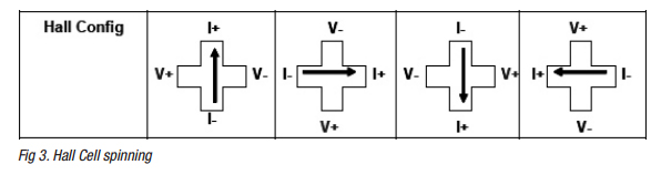
A technique difficult to realize in discrete components is the spinning of the Hall Cells. By placing the Hall Cell on an ASIC, an array of hall cells can be implemented and averaged. This combined with spinning of the Hall Cells results in a much more accurate current measurement. The spinning refers to the rotation of the current source and measurement points on the individual hall cell being rotated through four positions. The multiple Hall Cells, combined with spinning, results in lower offset and gain errors.
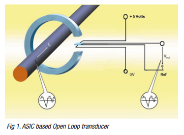
Perhaps one of the biggest advantages to the ASIC based transducer is in power supply selection. Traditional current transducers typically require a bipolar power supply (+/-15V for example). This gives an output that has a magnitude and polarity. The polarity indicates direction of current flow. In the ASIC based transducer, the power supply can be a unipolar 5V or even 3.3V. A unipolar transducer preserves the current direction information through the use of a reference voltage, typically 2.5V in a 5V transducer. This reference voltage indicates no current (0A).
The Reference Voltage
The reference voltage (Vref) is generated internally by the ASIC. The output voltage proportionally representing the current measured adds or subtracts from the reference depending on the direction of the current. Due to the ASIC output amplifier not being a rail-to-rail type, the output limits are 0.5V and 4.5V when power is supplied in 5 Volt unipolar. Depending on the sensitivity programmed into the ASIC, the range of output voltage from 2.5V to a respective limit might represent three times the nominal rated current of the transducer. This allows for measurement of the current for control and a 300% measurement for protection schemes if needed.
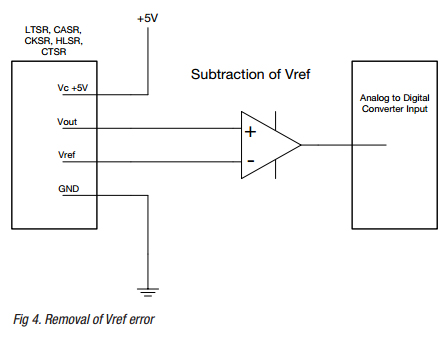
There is an uncertainty associated with the reference voltage. In most ASIC based transducers, the Vref is externalized on a pin for reference. The Vref is both an input and an output. The output function can be incorporated as an input into a differential amplifier along with the output voltage of the transducer (Vout). Subtracting the Vref from the Vout removes the Vref error from the measurement. Or the Vref and Vout can be input into two separate Analog-to-Digital inputs and subtracted in software. The Vref can also be an input with an external voltage applied to the Vref pin. This is useful in two ways, either as a more accurate source for the Vref than the one generated internally by the ASIC, or as a way to shift the Vref to another value. The Vref can be pulled higher or lower by applying the desired voltage to the Vref pin. This can open the range up in one direction of current flow. This is useful in unidirectional current flow applications where a broader range with a higher volts-per-amp output is desired.
Improved Reliability
The ASIC is a more reliable device than a transducer constructed with discrete components. An ASIC based transducer will operate over a broader temperature range than a discrete components device. This increased reliability and broader operating temperature range has led to the development of ASIC based current transducers for the automotive and industrial markets. Almost every car manufactured today has, as a minimum, battery current monitoring. Hybrid and electric cars will have more than a dozen current transducers in each vehicle. Automotive quality requirements have driven transducer development to ASIC based solutions. Unipolar power supplies, ratiometric capability, light weight (no potting) and rough environment reliability are some of the characteristics of automotive type transducers. The automotive families of transducers have found uses in other fields such as offroad vehicles and industrial equipment.
ASIC based transducers allow for additional features to be added. The latest ASIC generation allowed many more programmability options such as gain, response time, Over Current Detection (OCD) level, reference voltage level, low power mode and standby mode. Self-test features are possible. Dedicated output pins such as for OCD are possible. Offset and gain errors can be tested over a range of temperatures during manufacturing and compensation can then be programmed in. Filtering can be programmed with impact on bandwidth and improved response times.
Programmability
Of the programmable features perhaps the largest impact is from the OCD. Implemented as a pin from an internal open collector configuration, the OCD will change states during an overcurrent episode. The OCD threshold is programmable and may be outside the measuring range of the transducer. Thus the measuring range can be focused on the operating current range and the overload function will operate separately. The transducer measuring range might have a programmable filter set to 3.5μs response time for control purposes. The OCD will still respond in 2μs. Control is filtered with a higher sensitivity than would be otherwise possible if the protection function was included in the measured range. An OCD pin eliminates the need for a crowbar/comparator circuit. The overcurrent threshold could be 5 times the nominal current rating of the transducer.
Approaching Closed Loop
ASIC based current measurement is more than ten years old. Much has been learned in those 10+ years. The newer LEM HG2 Hall Generation 2 ASIC offers significant performance improvements. The performance of an HG2 based Open Loop transducer approaches that of a Closed Loop transducer. For lower fundamental frequency applications (<=400Hz) a LEM HG2 Open Loop transducer will provide bandwidth and response time close to that of a Closed Loop transducer. Uncertainty over temperature will fall closer to a Closed Loop’s performance than to the performance of a generation one ASIC device. This allows existing applications to perform better and applications previously requiring performance that an ASIC device could not provide can now be met with an ASIC solution. In addition to the performance improvements, the inclusion of an OCD output allows the measuring range to be more focused on the applications dynamic control range, further improving performance.
Conclusion
The implementation of ASIC based current transducers opens up functionality that the traditional discrete component transducers could never achieve. The availability of high reliability ASIC based transducers with expanded temperature operating range has opened up the automotive field to current measurement. Unipolar supply ASIC’s have simplified power supply schemes. Programmable OCD allows for more effective measuring ranges while still providing for overload thresholds. The development of the generation 2 ASIC devices further improves performance. With better performance and additional functionality the Gen 2 Open Loop devices are approaching standard Closed Loop performance. This allows existing Open Loop applications to implement the generation 2 devices and improve performance immediately. For new designs the generation 2 devices allow for more sophisticated implementations and possible outright replacement of a Closed Loop transducer.

About LEM
LEM is a market leader in providing innovative and high quality solutions for measuring electrical parameters. Its core products – current and voltage transducers - are used in a broad range of applications in industrial, traction, energy and automotive markets. LEM’s strategy is to exploit the intrinsic strengths of its core business, and develop opportunities in new markets with new applications. Together with production plants in Geneva (Switzerland), Machida (Japan), Beijing, (China) and our regional sales offices, LEM offers a seamless worldwide service. LEM has been listed on the SIX Swiss Exchange since 1986. The company’s ticker symbol is LEHN.
The content & opinions in this article are the author’s and do not necessarily represent the views of RoboticsTomorrow
Comments (0)
This post does not have any comments. Be the first to leave a comment below.
Featured Product