RASC-AL Exploration Robo-Ops Competition (i.e., Robo-Ops) is an engineering competition sponsored by NASA and organized by the National Institute of Aerospace. In this exciting competition, undergraduate and graduate students are invited to create a multi-disciplinary team to build a planetary rover prototype and demonstrate its capabilities to perform a series of competitive tasks in field tests at the NASA Johnson Space Centers Rock Yard in June 2013.

The RoboUtes | University of Utah
We were fortunate to be given the opportunity to show off some of the leading entries into the RASC-AL Exploration Robo-Ops Competition. Here are 5 of the design reports:
Worcester Polytechnic Institute
University of Nebraska-Lincoln
FAMU/FSU College of Engineering
The RoboUtes are; Nicklaus Traeden, Michael Bills, Abhijit Boppana, Matthew Monahan, Aditya Pandey, Jenni Orton, Jose Ortega, Jon Davies, Anh Luong, Enoch Lee, Daniel Henshaw With Professor Mark Minor PhD
Abstract
The University of Utah RoboUtes robotics competition team intends to compete in the NIA RASC-AL Robo-Ops planetary rover competition sponsored by NASA. For the competition, teams must build rovers that can reach and collect samples spread over a planetary analogue test site. To achieve the objectives of the competition, the multidisciplinary team will field a sophisticated teleoperated rover. This rover will utilize an innovative simple passive suspension system, a versatile robust sample collection effector, modern construction materials, and industry leading manufacturing techniques. Computation will be handled by a network of separated embedded systems to allow for simultaneous component development. The software architecture will be structured to allow for real time programming from a user friendly interface. Multiple daughter buggy systems will work in tandem with the main rover to facilitate faster sample collection and scouting. Signal from the user interface will travel to the rover through a Verizon Wireless USB modem. The rover will broadcast a WiFi signal to allow for user communication to the daughter robots. Local control of the rover will also be possible for testing and outreach purposes. The RoboUtes team will engage the community by promoting the excitement of space exploration. This will be achieved through a dynamic and expanding online presence, volunteer work, mentoring programs, hands on demos, and by cooperating with local partners and organizations. To accomplish this work the RoboUtes team will use wide array of available technical resources and will lean on the experiences of the previous rover designs.
INTRODUCTION
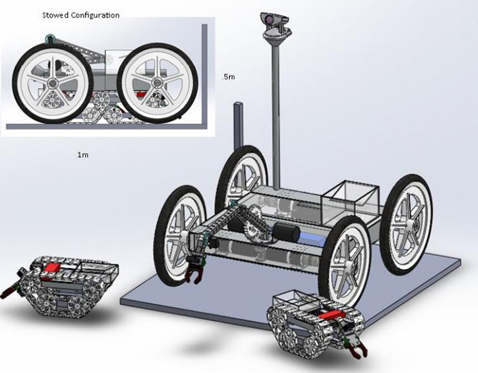
The National Institute of Aerospace (NIA) Revolutionary Aerospace Systems Concepts - Academic Linkage (RASC-AL) Robo-Ops competition represents an analogue to the challenges of actual planetary rovers. Planetary rovers handle extreme terrain and environments to perform scientific tests on collected samples. To simulate this, the competition rovers will have to navigate four different variable terrain fields and collect colored rocks, forcing the rovers to have a robust suspension and drive assembly and versatile sample collection system. Existing surface rovers rely on either a radioisotope thermoelectric generator or solar panels for power. Because of this, the rovers usually have slow movement speeds so path determination efficiency is critical. To maintain this level of critically with higher power competition vehicles, a one hour time limit is established. The RoboUtes team has designed a capable terrain traversal and sample acquisition platform designated COLE Mark II, or Cellular Operated Land Explorer Mark II (referred to variously as “COLE”, “the robot”, or “the rover” throughout this documentation.) The COLE Mark II platform features a sturdy passive suspension system and a dynamic five degree of freedom manipulator arm. The RoboUtes team hopes to mitigate the time constraint by utilizing two daughter robots to gather easily obtainable samples and scout hard to get samples for the main rover. The RoboUtes team feels that this addition largely separates their design from previous rovers and is a valid step forward in planetary rover systems as it allows for a larger area to be scanned at the same time for a relatively low power, weight, and economic cost.
DESIGN CRITERIA
The RASC-AL Robo-ops competition is a teleoperated robotics competition held at NASA’s Johnson Space Center (JSC) Analogue Test Field, or Rock Yard. Rovers have an hour to traverse the various terrain types found on the field and collect and store multicolor painted rock “samples.” These rocks range from 2 to 8cm and weigh no more than 150g. The rover must have a stowed configuration of 1 meter by 1 meter by 0.5 meters tall. It must be able to climb and descend grades of 33%, cross sand, and clear obstacles of at least 10cm. The rover will be teleoperated from the RoboUtes home campus at the University of Utah (UofU), a distance of approximately 2,000Km. The rover receives commands through a Verizon Cellular Modem. Expected communication speeds are ~0.4 Mb upload and ~0.6 Mb download. Latencies of 150-300 ms are expected. Rover and Mission Control operations need to be posted online on the competition website and the team website and must be easily accessible from social media sites.
HARDWARE SYSTEMS
Chassis and Suspension
COLE’s main structural components will be fashioned from 6063 aluminum rectangular tubing. Aluminum is strong, affordable, and easily machined, making it an ideal choice for robotics systems. The 6063 alloy beam sections will be TIG-welded, allowing for strong, permanent, lightweight joining of chassis elements. The smooth surface allows for easy anodizing to protect against corrosive environments.
6061 aluminum sheet will be welded in as a lower decking to support major components (batteries, motors, sample collection arm, etc), but wherever possible, lightweight polymers or composites will be used to form COLE’s body. Polycarbonate sheeting will be used to enclose and protect components in vulnerable areas of the robot (such as the underbody), while lighter, cheaper, vacuum-formed thermoplastics will be used in areas where there is less danger of impact damage. Materials are being selected with low weight and high impact resistance as high priorities. Previous implementations of COLE have used heavy, brittle materials like acrylic to enclose electronics. Not surprisingly, this has lead to a significant amount of breakage and rework. With closer attention being paid to material selection, the new design will be simultaneously lighter and less prone to breakage.
The RoboUtes’ signature dual-platform suspension system will be returning for 2013, but with a significant revision. Careful observation of last year’s rover revealed that having a “yaw” degree of freedom was complicating driving software significantly without adding any noticeable improvement in off-road capability. As such, the new design will feature a spine-based suspension system that uses only “roll” to adapt to terrain. Ground clearance remains high, and the increased stiffness of the chassis will allow the rover to climb and descend with fewer tendencies to ‘fishtail’ or buckle like older designs. The remaining degree of freedom causes the rover to maintain four wheel contact at all times, allowing the rover to climb over large obstacles without risk of tipping
The two chassis platforms will be connected by a bearing grade bronze shaft and bushing system to allow the two platforms to rotate relative to one another about the axis of the shaft. The shaft will be hollow and unobstructed to allow for voltage and signal wiring to pass freely between the two platforms, completely enclosed and protected from the elements.
Wheel and Drive Assembly
The two hub chassis system forces four motors to be used to drive the wheels. These motors will be located on the inside of the chassis hubs, directly connected to the wheel shaft with a coupler. The keyed wheel shaft is supported by a bearing on either side of the frame to prevent loads on the wheel from being transferred to the motor shaft. The wheel shaft will key into a keyed machined adaptor plate that will fit onto the wheel. The wheel’s basic form factor is a sixteen inch diameter. Motor torque has been calculated to move the maximum weight rover up the required grade with this size wheel at acceptable speeds. The polyethylene pneumatic tires used on last year’s rover are lightweight, reliable wheels that will be used in primary development. Custom wheels that incorporate lighter materials, increased traction, or increased damping will be evaluated in secondary development, after the rover is driving effectively.
Sample Collection System
COLE’s sample collection arm will be articulated at five different points; the turntable, the shoulder, the elbow, the wrist, and the gripper. The turntable will be actuated by a servo motor, and be capable of rotating a maximum 360 degrees. The shoulder link will be directly connected to a gear motor, and be able to rotate close to 180 degrees. The elbow will be actuated by a gear motor turning a double-crank four bar linkage, allowing for the weight of the motor to be divorced from the joint itself, reducing the forces and moments acting against other components, and allowing around 135 degrees of rotation. The wrist will be actuated by a small servo motor, and will be capable of rotating around 90 degrees. The gripper will be actuated by a small servo, and will be capable of gripping samples of any allowable dimension. Having four degrees of freedom plus a gripper expands the available working area and allows the rover to pick up rocks in nested locations or when the rover chassis is tilted.
The main structural components of the arm will be made from ¾” 6061 square tube aluminum, while the connecting pieces will be machined from ABS plastic. Gears and linkages will be cut on a water jet from mild steel, aluminum, or plastic as appropriate to keep moments generated on the arm as low as possible. All rotating surfaces will be equipped with bearings or bushings for smooth, efficient operation. Mounting provisions will be made to attach potentiometers or absolute position encoders to transmit position data to the arm control electronics.
The RoboUtes team has performed exhaustive testing on multiple gripper types at multiple form factors in varying positions for various rock configurations. This testing has resulted in a simple two finger gripper with a high friction surface being chosen for last year’s rover. Primary development will again use a two finger gripper with a rubberized gripping surface. Secondary development will iterate this design to achieve optimal shape and most appropriate friction inducing material.
Sample storage will be located at the rear hub of the rover within easy slewing distance of the arm. A light, strong, vacuum-formed thermoplastic bin with a labyrinthian structure will allow samples in but not out when the rover is traversing large obstacles.
Sensor Support Systems
The RoboUtes will be utilizing a stowable mast to elevate the rover’s main camera to a more human-like perspective. For transportation and rough driving, this camera mast will be stowed to fit within the size limitations of the competition. Mission Control will be able to decide at any time to deploy the mast, which will be actuated by a compressed-gas lift piston. This decision should not be made lightly, as the mast will not be re-stowable for the remainder of the run. This system has the added benefit of passive pneumatic damping to stabilize the camera once it is fully deployed. This arm system will actuate the sensor boom when moved for the first time.
Buggy System Hardware
The buggy system is designed for optimal mobility over sand or loose gravel terrain. This is accomplished by the use of tank tracks. These tracks will be printed on the University of Utah’s recently acquired Objet Eden 360 V 3D printer. This printer is able to print up to seven different materials at a time. The RoboUtes team plan to use this feature to print structurally sound tracks with a rubberized outer coating for increased traction. These tracks are pinned together using eighth inch stainless steel pins. The proposed system uses twenty-seven tracks that run on four cogs to give a 45 degree angle of attack. To support these tracks a 6063 aluminum chassis is used to rigidly connect the track cogs. Computer models of this track system reveal a weight of approximately 0.64lbs per track assembly. Geared motor shafts are directly connected to the forward most cog to provide the highest power transmission while keeping the motor away from ground obstacles. Aluminum cross beams connect two sets of tracks and support polymer decking material to house electronics and secondary mechanical systems. The entire buggy is estimated to be approximately 6.5” tall so it will fit under the main rover.
A single degree of freedom arm with a two finger gripper will be located on the front of the camera. The arm and gripper will be driven by servos. The arm servo will rotate a full 180 degrees to allow the arm to move up around the buggy and drop the rock in the small sample collection bin. The main rover arm will be able to pick up rocks out of the sample collection bin. Secondary development will allow the buggy to dump it’s samples for faster transfer to the main rover.
Buggy Deployment and Support
The buggy systems will be deployed at the beginning of the competition time by a passive device connected to the arm. As the arm deploys from a stowed configuration, it will pull a cable, releasing both buggies and the sensor boom. Secondary development will include a ramp to allow buggies onto the upper deck of the chassis to dump buggy payloads into the rover collection bin.
ELECTRICAL SYSTEMS
Computational components
An onboard ITX computer system serves as the video processor and acts as a pipeline to send commands to the drive and arm boards. This computer is running in a linux operating environment This computer has an ethernet connection to the onboard router and runs on 12 volts. It communicates to the Arduino’s and receives camera feeds via USB. The drive Arduino Due receives commands and power from the USB. It takes in the signal from the through hole encoders and sends signals to the Pololu high voltage motor controllers. The arm Arduino Due also receives power and commands from the USB line. It reads the two arm potentiometers on its ADC inputs and sends signals to the two motor controllers for the shoulder and elbow joints of the arm. To effectively power the servos, the Arduino will be connected to an Adafruit PWM servo driver that relays the signal to the servos at higher power.
Video Systems
The rover’s vision needs will be fulfilled by three video cameras. Primary vision will be provided by a Canon VC-C50I, a high-resolution security camera with integrated pan, tilt, and both digital and optical zoom. This camera will be mounted on an elevated mast to obtain the best possible perspective. Additional vision will be supplied by two low-end web cams, mounted at the nose and wrist of the rover. These cameras deliver a much lower quality video stream than the mast camera, but at much lower monetary and bandwidth expenses. These coarser images will be adequate for basic navigation and object manipulation, leaving the mast camera free to scout for nearby samples.
Sensor Implementation
The RoboUtes will be collecting angular position and velocity data from each of the four drive wheels using through hole optical rotary encoders. This data will be interpreted by the computer to vary the serial signals to normalize the speed of all four wheels. This will give the system the ability to compensate for non-ideal situations, such as motor load discrepancies, that could otherwise cause a motor to lag behind the others and affect steering and chassis loads.
Sensing for the sample acquisition arm will be especially critical, as the arm will feature automated software functions that will require position data in order to execute properly. The arm’s 2 gear motor joints will be tracked by potentiometers or absolute position encoders to identify their positions. The arm’s other 3 degrees of freedom will be actuated by servo motors, which are conveniently self-sensing and need no additional electronics.
For additional peace of mind, the sample acquisition arm will also be outfitted with electromechanical limit switches at each of its range of motion extrema. These switches will prevent the actuators from being energized if the system has already reached its limit of travel in that direction, which will eliminate much of the arm’s breakage risk. The sensor boom will also host antenna systems to boost WiFi, GPS, and Verizon connectivity.
Power Structure
The RoboUtes typically turn to one of our 20 amp hour, 24 volt, lithium iron phosphate batteries to power any given project. These batteries are quite exceptional for prototyping, but somewhat overkill for the scope of the competition run. Even with all systems running continuously and all motors stalled, these batteries could still (theoretically) run the rover for longer than the competition duration. As such, a lighter 24 volt battery is planned for competition. Charging and discharging battery management circuitry is located on the battery to ensure safe operation at all times.
A 20 amp circuit breaker will be wired in line with the battery, to provide both normal and emergency shutoff capabilities. The rover requires a variety of different voltages to power its components handled by three high efficiency voltage buck boost regulators to provide 12, 6, and 5 volt rails for the various computers, controls, and actuators featured on the rover.
Buggy Electronics
The buggy will be controlled using a Raspberry Pi model B computer. This module will connect to two motor control boards for the drive motors and a servo power system for the arm mechanics. The battery on the buggy will be a 7000mAh 14.4 volt lithium polymer battery. A video shield board will be used with the Raspberry Pi to compress and relay the video feed from the onboard camera.
SOFTWARE SYSTEMS
This year’s RoboOps entry will feature a very capable main rover equipped with two daughter buggies. This system is inherently more complicated than our previous entries, however, elimination of the “yaw” joint in the spine, the use of servos in the wrist, and the use of only one PTZ camera mean that the software architecture for the COLE Mark II rover will be much simpler. The onboard software needs to be able to accurately control the mobile functions of the platform while providing Mission Control with video and sensor feedback data . In order to streamline the rover’s competition operation, a number of functions will be automated. Tasks that previously put a great deal of strain on the human operators in Mission Control, such as returning samples to the collection bin, will be made relatively painless. The software will provide Mission Control with a GUI that allows them to effectively control the rover and buggies, monitor a great deal of incoming status data, and even reprogram microcontrollers in competition situations.
Drive Software
The drive system will be controlled by an Arduino Due. Since this rover utilizes slip steering to turn, the software will contain left drive and right drive variables. User input will alter the magnitude of these variables based on joystick orientation. The microcontroller will send commands to the four motor controllers and check encoder values to maintain identical front and back wheel speeds. In secondary development, the drive Arduino will read calibrated accelerometers located on both chassis hubs to allow for proper wheel speed calibration when traversing obstacles.
Effector and Manipulator Control
COLE’s manipulator arm will be controlled via a dedicated Arduino Due. This Arduino will receive commands from the main computer and will read them with interupts so no data is lost. Multiple limit switches and position sensors will provide the software with exact data on the current states of the arm, such that automated executables can replace many tedious tasks that were previously the burden of the operator. The arm will initially be in a ‘stowed’ position, and will be brought to a ‘ready’ position by an executable. Once the arm is ‘ready’, the operator will assume manual control of the arm. Sample retrieval will be pre-programmed so that once a human controller secures a sample, a single-key command can be executed to direct the arm to place the sample in the holding area, and return to the ‘stowed’ position to prepare for travel. The Due board will run a tuned PID control loop for both the shoulder and the elbow motors to move it to the desired position. PID control stands for Proportional Integral Derivative control, and allows for relatively rapid and accurate control of electromechanical systems. These operations will save time and bandwidth, as well as reduce the chance of losing a rock due to human error or communication latency.
Video Processing
Due to video processing’s relatively high computational expense, COLE’s main computer will manage all video related tasks. These include processing and compressing video from COLE’s cameras and transmitting it all back to Mission Control. COLE will also manage the articulation of its own PTZ camera based on commands from Mission Control.
User Interface and Teleoperation
RoboUtes Mission Control will feature a robust Graphical User Interface capable of managing all of COLE’s competition-critical systems. The primary feature of the GUI will be to transmit movement commands from Mission Control to COLE and the buggies. The GUI will also receive all of the incoming video data and route it to the appropriate controller to be used by COLE’s operators, and streamed on the RoboOps website. It will interpret operator commands from Xbox controllers. The GUI will provide remote access to COLE’s main onboard computer when needed, to allow for Arduino controllers to be re-programmed without making any physical connection to the rover. The GUI will also provide various useful data to Mission Control such as signal strength between COLE and buggies, remaining battery strength, sensor information, and GPS telemetry.
Remote Programming
Thanks to the simplicity of the Arduino programming environment, all of COLE’s Arduino-based systems will be remotely programmable to allow for emergency ‘hotfixing’ as well as more convenient uploading during normal software development. There are a number of ways to accomplish this and integrate the Arduino’s systems into the GUI used back at Mission Control. One possible route is to make a small, low-bandwidth program that could run on COLE and interface with both of the Arduinos. This light program would directly interface with the GUI back at Mission Control, and receive pre-compiled code to write directly to the Arduinos. Alternatively, COLE’s GUI could be remotely accessed and run the Arduino development software onboard. This method would certainly be simpler to implement, but would come with a significant bandwidth cost. Further research will be required to determine the most feasible solution. The Raspberry Pi’s contain a full system architecture, so remote login is possible on the buggies as well.
Buggy Software Architecture
The primary tasks of the Raspberry Pi computers are receiving and transmitting video, receiving movement commands from Mission Control and controlling mechanical actuation on the buggies. To perform the movement tasks, the computer will relay commands to appropriate motor control electronics. Interupts will be used to ensure proper communication. The Raspberry PIs have enough computational power to manage all of these tasks, and can even compress video in real-time to save bandwidth on COLE’s wireless router.
COMMUNICATION SYSTEMS
Multiple communication protocols will be used in the total system hardware. These protocols are implemented for ease of use, signal to noise, and bandwidth properties. Onboard processors will communicate with each other and Mission Control.
User to Robot Communication
Users will interact with controllers for rover operation in Mission Control. The Mission Control software will compress the information and relay it to COLE’s onboard ITX computer over a Verizon Wireless broadband connection provided by a wireless modem. This modem will be installed on an onboard Cradlepoint wireless router that will have an ethernet connection to the ITX computer. COLE’s computer will send compressed video packets back over the same line to Mission Control, as well as any requested sensor information.
Inter-chip Communication Protocols
Multiple chip to chip communication protocols are implemented in the system architecture. The router communications will go the the ITX computer via an ethernet connection. Packets will be sent to the Arduinos from the ITX via USB. To send these commands to motors, the Arduinos will process them and send using serial communication protocols. To actuate the servos, the Arduinos will send I2C commands to an Adafruit servo driver which will convert a relatively small amount of data to the larger continuous PWM signals. This board frees up more processor time to run the PID control software.
User to Buggy Communication
To control the buggy, Mission Control operators will send signals from controllers. Again, Mission control will send data to the Raspberry Pi through a Verizon Wireless broadband connection. This connection will be facilitated by a secondary wireless modem and router located on the main rover chassis that will be broadcasting WiFi. The Raspberry Pi model B board is able to connect to this WiFi signal without additional components. Compressed commands will be sent to each of the two buggies. These commands will be processed and commands will be sent from the Raspberry Pi to the servos and motor controllers using PWM and serial communications protocols, respectively. A camera shield board on each Raspberry Pi will process and compress the video from the onboard webcam, which will then be sent back over the WiFi connection. Protocols will be established to stop operations and search for the WiFi signal if connection is lost. RoboUtes team members hope to establish autonomous ‘return to rover’ functionality in situations of sustained communication failure. This system or something similar will be addressed in secondary development
Local Operation
COLE will be locally driveable via a USB wireless XBOX controller connected to the main computer, using similar software architecture as the remote drive. Local driving will allow for convenient yet high-function operation for troubleshooting and demonstration purposes.
SEASON TIMELINE
Primary Development
The same day that funding for the robot is secured, the RoboUtes team will purchase raw materials from online retailers and begin manufacturing necessary components on the multiple available advanced 3D printers. Shipping is estimated to take approximately one week. The chassis structure and drive system machining, welding, and assembly is expected to take two weeks. Electronics, wiring, drive system, and communication troubleshooting is expected to take one week. This means that COLE Mark II will be driving within four weeks of receiving funding. This timetable is significantly accelerated from previous years to allow for more time for optimization and troubleshooting. Such a timetable has been made possible by the significant suspension system simplifications that have been made, as well as by the growing body of knowledge and experience now possessed by the RoboUtes team.
Separating drive and arm control electronics allows for simultaneous development of both components. Again one week is expected for raw materials to be delivered after initial purchase. More machining and construction is required to create the arm and attach required sensors, so the arm development is expected to take three to four weeks of manufacturing time. The control architecture is also expect to take three to four weeks, due to the complex nature of the system and the PID tuning required. Integration with the chassis and troubleshooting communications is anticipated to take one week. The primary arm and gripper system is expected to be in operation approximately eight weeks after parts are received.
User interface layout and operation will be developed as soon as the proposal is accepted by the teams’ computer science specialists. Software architecture for the main computer on COLE will also be developed with the user interface to allow for proper communication across the Verizon signal line. Rudimentary control systems are expected to be in place before the electronics are placed in the chassis, with additional features added in secondary development.
One buggy system will be fabricated in primary development. Printed components will be requested as funding is secured. Because these components take time to create, the main focus of the team will initially be on the main rover arm and drive systems. Buggy development is expected to take two to three weeks after all components are available. Raspberry Pi system architecture and communication abilities will be developed by computer engineering members from the start, as they have substantial prior experience with the platform.
Secondary Development and Testing
Secondary development will begin as soon as the minimum required functions of the rover are working correctly. This phase will focus on evaluating and iterating the existing system to improve efficiency and lower weight. The iterations will be developed so that the rover is never out of operation for more than a few days. To effectively iterate designs, rigorous testing will take place during this phase to ensure the robust nature of all the components. In secondary development, two Raspberry Pi’s will be connected to test multiple buggy communication feasibility. If two systems can be run reliably, then fabrication of a secondary buggy system will match the iterated first buggy design. Operator testing and training will occur during this phase. Secondary development and testing will continue until the competition date.
EDUCATION AND PUBLIC OUTREACH
The RoboUtes believe that developing a strong network of community interest and support surrounding our projects is crucial to our continued success as a team. In addition to the Facebook, internet, and Youtube presences proscribed by the RoboOps competition, the RoboUtes strive to make frequent appearances and demonstrations in the community to help build interest in our team, RoboOps, NASA, and math and science in general.
To this end, we have developed strong relationships with a variety of other groups working in and around our community, including; FIRST Robotics and FIRST Lego League, The University of Utah Department of Physics and Astronomy, The Leonardo Contemporary Science and Art Museum, The Bryce Canyon Astronomy Festival, The Natural History Museum of Utah, The Maker Faire, and many others.
Through these partnerships, we have been able to hold demonstrations, meet-and-greets, and presentations that we feel have had a positive/inspirational impact on the lives of many people from our community. For 2013, the RoboUtes are looking to take outreach efforts to the next level. In pursuit of that goal, we have petitioned the Associated Students of the University of Utah assembly for funding to purchase both Lego Mindstorms and Arduinobased robotics demonstration kits. The RoboUtes have been granted this funding, and are currently in the process of developing a curriculum for a basic introduction to robotics appropriate for students of all ages and skill levels.
We feel that adding a component of hands-on, experienced-based education to our outreach program will help to add real meaning and impact to what we are trying to do in the community. Additionally, the RoboUtes will be continuing with our usual schedule of demonstrations and appearances at science and engineering events in the community. Ideas for improving our internet presence, creating an engaging EPO video, and doing more traditional media outreach (television, radio, print, etc) are all being carefully considered for the 2013 competition.
TEAM AND FACILITIES
The RoboUtes are an interdisciplinary team based out of the University of Utah's College of Engineering. The team consists of both undergraduate and graduate level students from a wide variety of disciplines, including Mechanical Engineering, Electrical and Computer Engineering, Computer Science, Robotics, and more. The RASCAL RoboOps competition and other similar ventures give RoboUtes team members an opportunity to collaborate with each other to apply what is taught in the classroom to a real-life applications.
The RoboUtes are under the advisement of Dr. Mark Minor, who received his PhD in Mechanical Engineering from Michigan State University in 2000. Dr. Minor’s research is focused on the design and control of robotic systems, making him a very valuable asset to the team.
The University of Utah Department of Mechanical Engineering has generously given the RoboUtes their own dedicated lab space for the 2012-2013 competition season, which will be used for design, assembly and testing of COLE’s various electrical and mechanical systems. Additionally, the RoboUtes enjoy access to the University’s Computer Aided Design and Engineering lab, the Student Machine Shop, the Advanced Machine Shop, and other facilities. These labs offer a variety of both traditional and cutting-edge fabricating machinery, including but not limited to: mills, lathes, welders, sheet metal brakes, a water jet cutter, laser engravers, Fused Deposition Modeling machines (3D printers), injection molding equipment, a vacuum forming table, Digital Logic Analyzers, various IC development boards, and reflow and rework stations.
The RoboUtes’ unofficial motto is ‘built not bought’. We believe strongly in developing our own solutions to problems and then building and refining those solutions in-house. This strategy is certainly more difficult and time consuming than buying an off-the-shelf solution, but in the end we feel it is more educational, more effective, and quite frankly, just more fun. The RoboUtes have the people, the places, and the tools to get the job done.
MISSION STRATEGY
Phase 1: Observation and Preparation
Assuming that the RoboUtes are not scheduled to compete very first, the observation of other competition team’s runs is very helpful in establishing the general ‘lay of the land’ of the rock yard, and in getting an idea of where sample rocks are likely to be found on the field. Mission Control will use observations from other team’s runs to plot a tentative rock collection route.
Phase 2: Startup
COLE’s 2013 software will be designed such that the RoboUtes ‘Away Team’ will be able to power up the rover, and all system initializing, sensor calibration, and network connectivity will be carried out automatically. After communication and control have been successfully booted, Mission Control will begin to send commands to ensure full functionality of the Pan/Tilt/Zoom (PTZ) mast camera, the 4 drive motors, and the 5 arm actuators. If full or adequate functionality is confirmed, Mission Control may begin roving with COLE, and move on to testing communication, control, and functionality of the buggy systems.
Phase 3: Roving
Mission Control will guide COLE along the tentative route plotted during Phase 1. At any time during Phase 3, Mission Control may decide to send COLE a signal to deploy the PTZ mast from its stowed position, to better view the competition field.
Phase 4: Buggying
COLE may deploy up to 2 ‘daughter’ buggy systems to make better use of its time on the field. Once deployed, the buggy(s) will be controlled by a dedicated driver and navigator. The buggy(s) will search for samples and potentially acquire them if they are placed conveniently. If not, they will be marked for possible future collection by COLE.
Phase 5: Sample Acquisition
As COLE approaches a sample, Mission Control will send COLE a signal to shift the sample arm from a stowed to a ready position. When the arm is ready, Mission Control will take manual control of the arm, and use it to acquire the sample. After the sample is deemed reasonably secured, Mission Control will send COLE a signal to automatically place the sample in the storage bin, and return the arm to the stowed position.
Phase 6: Endgame
As the competition hour comes to an end, Mission Control must decide to either continue collecting samples until time expires, or to return to the top of Mars Hill for bonus points. Mission Control must also allow time for any deployed buggies to return to COLE and transfer any samples acquired to COLE’s holding area. When time expires, Mission Control will send COLE the signal to power down, and the run will be over.
Phase X: Diagnostic and Repair
In the event of a failure, the arm (if operable) will be deployed, and its camera system will be used to inspect for physical issues impairing the rover. COLE’s main computer will be accessed remotely to address software issues, and potentially solve them (for example, uploading an open-loop arm control script to compensate for a malfunctioning potentiometer). In the event of a failure beyond the scope of the rover to self-repair, competition officials will be contacted and the ‘Away Team’ will be sent in for a mulligan.
LESSONS LEARNED
2013 will hopefully be the University of Utah’s RoboUtes Robotics Club third consecutive year of competing in the RASC-AL RoboOps Planetary Rover Competition. The competition has been an incredible educational experience for everyone involved, making us all more well-rounded and capable future engineers.
Perhaps the greatest lesson the RoboUtes have learned in previous competitions is the incredible importance of iterative and simultaneous design. Rough drafts and prototypes are essential for developing good solutions to problems. Trying to solve all problems and optimize all systems in a single implementation of a design is a daunting task, and has often left the team with insufficient time to troubleshoot systems.
Moving forward, the RoboUtes have resolved to design and build towards short, attainable goals. These ‘primary development’ goals will be mission-critical functionalities, like ‘driving’, ‘manipulating the arm’, or ‘communicating via the internet’. Once functionality has been achieved in these areas, the team will be free to move on to secondary development, where ideal functionalities can be pursued, like ‘driving faster’, ‘automating the arm’, and ‘communicating massive amounts of data via the internet.’
Similarly, the RoboUtes have learned that is important to consider the true objectives and requirements of a design, rather than trying to optimize all possible variables. For example COLE Mark I had 3 simultaneous camera feeds broadcasting at any given time, 6-8 hours of battery life, and was capable of climbing over obstacles over 16 inches in height. These were ‘cool’ features, but in the competition itself, they were of little help. The winning teams had robots with worse cameras, shorter battery life, and very limited off-road capabilities, but they were really good at driving around, and picking up rocks. Focusing on the task at hand will help the RoboUtes to be much more successful in the future, and ideally give us more free time in the long run to implement ‘cool’ but non-critical features.
Finally, past experiences have lead the RoboUtes to aspire to make design choices for COLE that are sustainable and functional throughout the entire design life of the project. For example, many parts of previous rovers have been made from acrylic sheet. This acrylic was not chosen for its impact resistance, its weight, or even its cost; it was chosen because it was easy to make parts out of quickly. The team was able to move quickly from concept and CAD drawings to reality, but in the long term, the material choice was not ideal. The acrylic was heavy, it cracked, and it cost a lot of money. 2013’s design choices will be made with the long game in mind- based on what is going to be best for design, fabrication, competition, and disposal, not just what is easy right now.
The content & opinions in this article are the author’s and do not necessarily represent the views of RoboticsTomorrow
Featured Product