With 3D CAD software, designers can actually simulate a robot's capabilities by reviewing how the robot's construction will be effected by the selected materials.
Len Calderone for | RoboticsTomorrow
Robotics is becoming a very important part of our lives. The design process is changing rapidly as the demand increases. As more industries are introducing robots into their workforce, three dimensional CAD solutions are keeping pace. Because of this, companies can see what the material is like and use this knowledge to design the products, while estimating costs.
With 3D CAD software, designers can actually simulate a robot's capabilities by reviewing how the robot's construction will be effected by the selected materials.
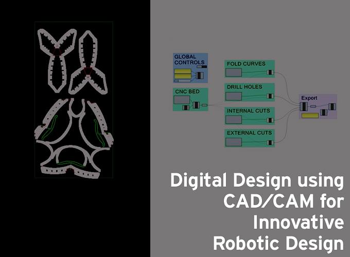
The next generation of robotic fabrication techniques opens up new opportunities for design conjecture as well as tackling building performance. CAD can be used to design curves and figures in two-dimensional space (2D), or curves, surfaces, and solids in three-dimensional (3D) space.
The designers of robots need powerful software to design their sophisticated robot systems. This software must be capable of being scalable across multiple robotics applications and tasks, and be able to incorporate any existing algorithms. Single software architecture, for both simulation and implementation, should expedite the design cycle and promote innovative robotics research to solve problems.
CAM is a subsequent computer-aided process after the computer-aided design (CAD). A model generated in CAD and verified in CAE can be placed into CAM software, which then controls the machine tool.
A CAD program helps create computer models defined by geometrical parameters. These models typically appear on a computer monitor as a three-dimensional representation of a part or a system of parts, which can be readily altered by changing the relevant parameters. CAD systems enable designers to view objects under a wide variety of representations and to test these objects by simulating real-world conditions.
The CAM program takes the CAD geometrical design data and controls the automated machinery. CAM systems are associated with computer numerical control (CNC) or direct numerical control (DNC) systems. Using both CAD and CAM programs in combination, it is possible for the processes of design and manufacture to be highly integrated.
The CAD design allows the designer to see the precise geometric shapes of a robotic product from all angles on the display; and the software can simulate the reaction of one part against new or existing parts for strength and stress.
With the design data stored in memory, the user can obtain printed copies of the drawing and specifications relating to any part or product quickly. The existence of a number of alternative designs provided by the database enables a designer to review multiple possibilities and to determine the best design for the concept. This lowers the cost of creating the product and reduces the time of marketing new products.
Many CAD/CAM software tools are highly specialized, resulting in a multi stage manufacturing process, such as is used for complex products like robots, and requires more than one CAD program to design and integrate the various parts.
Technical progress has addressed many of the aspects of CAD/CAM systems. The use of personal computers emerged as an alternative to older mainframe- and workstation based systems. The greater viability of personal computers for CAD/CAM applications results from their ever-increasing processing power and comparatively low costs.
There is a trend toward the standardization of software, so that the data in different packages can be readily shared. Standards have been established for some time regarding data exchange and graphics, and the X Windows System and Microsoft's Windows are becoming established as industry standards for user interfaces. This technology has helped in the creation of new innovative robotic products.
Inspired by the motion of an elephant’s trunk, Festo AG developed the Bionic Handling Assistant, a mechatronic arm that can work closely and safely with humans. Unlike other industrial robotic arms, which are typically enclosed in safety cages to protect nearby workers, the Bionic Handling Assistant is designed to interact directly with humans. Incidental contact with the mechatronic arm is harmless because the arm is made of lightweight polymer components driven by compressed air. Also, the pneumatics are managed by a control system that yields immediately in the event of a collision.

The researchers at Festo developed the control system using MATLAB® and Simulink® for Model-Based Design, and then implemented it on a programmable logic controller (PLC) using Simulink PLC Coder™. With a model-based design, the people at Festo can model, simulate, optimize, and generate code to implement the controller all in the same tool environment.
Flexible Robotic Environment (FRE) software is written by Bicommerce LLC, Rapid City, S. D., and the software also acts as a motion platform. This new software optimizes kinematics; and it plans paths for custom robots that handle multiple axes.
The FRE-based VDK 4000 is a modular direct-write six-DOF machine consisting of linear and rotary-motion components from Aerotech. To build a robot with FRE, the integrator selects compatible motors, drives, and mechanical parts. The software calculates how motors on each axis must move to trace the robot’s end effector through preset points in space.
The Application Programming Interface (API) software defines the motion profiles of the paths. The API is a graphical CAD-to-motion path planner called ModusCAM. Depending on the application, the API creates three kinds of paths — stand-alone, typically to drive inspections; paths to clad surfaces of 3D solids; and paths to build solids slice by slice. The API can also plan paths for machining solids.
The demand for new large range robots with hydraulic actuators is increasing. These robots automate several important construction tasks. The design of these robots is based on the 3D kinematics CAD toolbox for robot simulation and software modules linked to a 3D dynamics simulation package. These robots work in new on-site applications, such as wall erection, material transport, interior finish work, and concrete distribution.

Construction robots work alongside people, and carry out jobs that pose a safety risk to construction workers. They also manage complex tasks that require a high level of technical expertise. Robots are an integral part of the manufacturing process and assembly lines, but are slow to be utilized in the construction industry.
Today, robots have a new role that takes them from science fiction to everyday reality thanks to digital design using CAD/CAM. Researchers are working to create some of the most innovative robotic designs. The Google-owned robotics company Boston Dynamics makes a number of stunning robots, one of which is the "Sand Flea," weighing only eleven pounds that can jump, and jump high.
It rolls across the ground like a remote control car, but the operator can get it airborne by sending a signal. Then, the Sand Flea props itself up at an angle and fires a piston into the ground that sends the robot hurtling through the air at heights of up to 30 feet. It can also hop through windows or doors, on to tables and even up staircases.
We can expect more innovative robots as CAD/CAM drives the designs.
For further information:
|
Len Calderone - Contributing EditorLen contributes to this publication on a regular basis. Past articles can be found with an Article Search and his profile on our Associates Page He also writes short stores that always have a surprise ending. These can be found at http://www.smashwords.com/profile/view/Megalen.
|
 |
The content & opinions in this article are the author’s and do not necessarily represent the views of RoboticsTomorrow
Comments (0)
This post does not have any comments. Be the first to leave a comment below.
Featured Product