Measured performance is at the level expected and increases the range of applications which may be addressed by open loop transducers instead of more complex solutions.
New Open Loop Current Transducers With Near Closed Loop Performance
David Jobling | LEM
Open loop current transducers using silicon Hall effect devices are based on a simple design concept and are inexpensive to manufacture, but their simplicity comes with some performance limitations. These limitations may be overcome by using closed loop architecture for some current ranges, but the downside is a more costly and physically larger design. This paper describes new open loop transducers using a dedicated Application Specific Integrated Circuit (ASIC), which bridges the performance gap between today’s open loop and closed loop transducers.
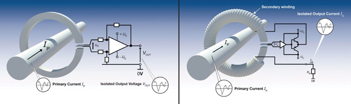
Fig. 1: Open Loop (left) and Closed Loop transducers
Introduction
Figure 1 shows the principle of operation of open and closed loop current transducers using the magnetic field of the current measured. Both may use a Hall cell integrated in the ASIC as the magnetically sensitive element, and both have the advantage of isolation from the measured current and a wide frequency range including DC.
In the open loop transducer, the Hall cell voltage output is amplified to output a copy of the measured current. However, any variation in the Hall cell sensitivity, such as with temperature, gives an error. The electrical signal at the Hall cell is very low, so the desire for a fast response time tends to give a noisy output because the signal bandwidth must be wide. Typically, the ASIC signal bandwidth must be larger than that of the current to be measured, because in order to overcome the offset and 1/f noise of the Hall cell its output must be modulated to a high frequency. This is accomplished by biasing the cell successively in the four orthogonal directions (‘spinning’ 1 ) and then demodulating after amplification.
In the closed loop architecture, the magnetic field induced by the measured (primary) current is exactly cancelled by a secondary current whose value is smaller by the primary:secondary turns ratio and is easily measured at the precise resistance RM. The exact sensitivity of the Hall cell is no longer of importance. Furthermore, the bandwidth of the signal from the Hall cell and its noise may be kept low, since at frequencies above a few kHz the current in RM comes directly from the primary:secondary transformer effect. These improvements, however, need a transducer construction which is more costly and which limits how small it can be made. In addition, the maximum measurable primary current is restricted by practical limits to the secondary current and the number of turns of the secondary winding.
The transducers described in this paper use an ASIC which allows performance near to that of a closed loop transducer but in which the design complexity is in the ASIC, not in the transducer. Once designed, this ASIC may be used in a range of inexpensive open loop transducers with different features.
ASIC and Transducer Details
Eight Hall cells are used to mitigate the poor signal-to- noise ratio at the start of the signal . Spinning at 1.5 MHz eliminates the Hall cell offset. Where the signal levels are low a differential architecture is used to give immunity from external dv/dt interference. After the signal is converted from differential to single-ended to economize die area, some selective screening is applied to critical nodes without using additional metal layers to maintain dv/dt immunity. A bandpass filter at the spinning frequency keeps the overall noise level low by limiting the noise bandwidth to that required for the response time, and by stopping aliasing of high frequency noise components into the signal frequency range. (The block diagram of the ASIC is shown in Figure 2.)
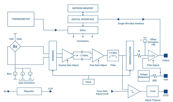
Fig. 2: Block Diagramn of ASIC Used in the New Open Loop Transducer
Quality standards in the automotive and, increasingly, in the industrial markets require that the ASIC be fully tested after packaging at two or preferably three temperatures. We take advantage of this to measure errors inherent in the open loop architecture and store corrections in the on-chip EEPROM. The Hall cell temperature dependence and the offset of the amplifiers after demodulation are corrected in this way.
The EEPROM memory also means that transducers can be configured according to a user’s preferences. For example, different reference voltages may be chosen and the output filter may be narrowed to reduce noise, or widened to reduce response time.
A new feature of this ASIC is the provision of a digital Over Current Detect (OCD) output from an intermediate point in the signal chain. The threshold level may therefore be above the level which saturates the conventional analogue output. Again, the exact threshold level may be chosen and stored in EEPROM according to different application needs.
Communication with the EEPROM is by a single wire bus to the ASIC output pin. This may be convenient even in the end user’s final application since this pin is likely to be connected to a microprocessor for signal processing.
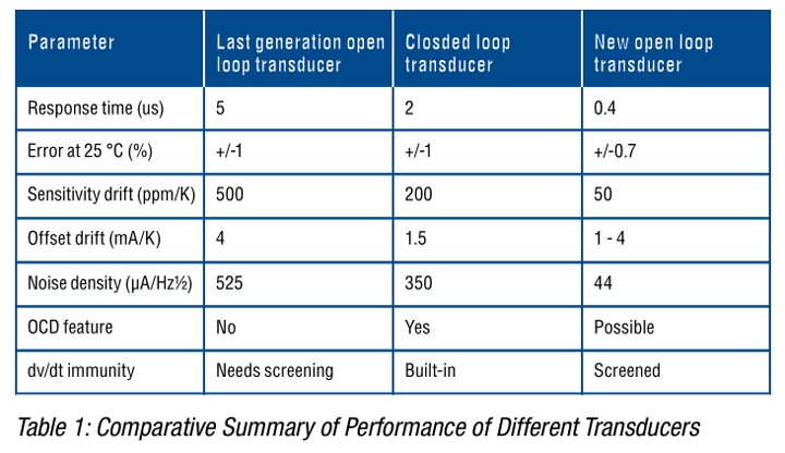
Table 1 summarizes some key performance parameters of new 25 ampere transducers compared with other open and closed loop transducers. In each case, the Hall effect is used as the magnetic detector. It shows that the performance of the new open loop transducers approaches and in some cases exceeds that of closed loop devices. The final choice of transducer in a given application depends on which parameters are most important for it.
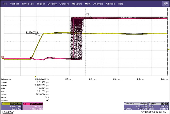
Fig. 3: Envelope of OCD Response
Figure 3 shows the digital OCD response to a current step on the transducer input. The response time of about 2 µs is due partly to the delay of the transducer magnetic circuit and partly due to a circuit that validates the presence of the over-current for at least 1 µs, to avoid triggering the OCD on short spikes. The envelope of the response is about 600 ns wide since the current step is not synchronized with the internal 1.5 MHz clock of the ASIC.
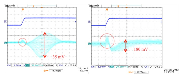
Fig. 4: Envelope of the dv/dt Response of Older Open LoopTtransducer (left)
and the New Transducer (right)
Figure 4 shows the immunity of the new transducer to dv/dt interference compared with an older design where external screening or grounding of the magnetic circuit would be needed to obtain an equivalent performance. The slope of the dv/dt signal is 5 kV/µs, and its amplitude is 1 kV. The delay between the dv/ dt signal and its effect on the output is due to internal sample and hold functions and filter blocks.
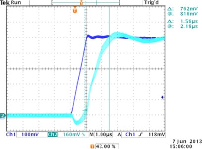
Fig. 5: Response to a di/dt Input
Figure 5 shows the step response of the new transducer to a primary current step. The response time is below 2 µs. However, the bandwidth of the 2nd order output filter may be reduced down to 1/6th of its largest value which increases the response time, but gives a corresponding reduction in output noise.
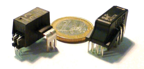
Fig. 6: Transducers
Figure 6 shows examples of two different current transducers using the ASIC described in this paper. No electrical components other than the ASIC are needed so their physical volume is very small. The magnetic circuit which concentrates the magnetic field at the ASIC is made of a low-cost ferrite which may be left floating due to the dv/dt immunity inherent in the ASIC design. The same ASIC is used in the two transducers whose performances may be quite different due to the configurations defined by the EEPROM and due to the primary and magnetic circuit arrangements.
Conclusion
New open loop current transducers have been presented whose performance approaches that of closed loop transducers. The key to good performance is an ASIC which was specifically developed to target these improvements. Measured performance is at the level expected and increases the range of applications which may be addressed by open loop transducers instead of more complex solutions. LEM — At the heart of power electronics LEM is the market leader in providing innovative and high quality solutions for measuring electrical parameters. Its core products — current and voltage transducers — are used in a broad range of applications in drives & welding, renewable energies & power supplies, traction, high precision, conventional and green cars businesses. LEM’s strategy is to leverage the intrinsic strengths of its core business, and to develop opportunities in existing and new markets with new applications. LEM is a mid-size, global company. It has production plants in Geneva (Switzerland), Sofia (Bulgaria), Beijing (China) and Machida (Japan). With its regional sales offices close to its clients’ locations, the company offers a seamless service around the globe.

About LEM
LEM is the market leader in providing innovative and high quality solutions for measuring electrical parameters. Its core products — current and voltage transducers — are used in a broad range of applications in drives & welding, renewable energies & power supplies, traction, high precision, conventional and green cars businesses. LEM’s strategy is to leverage the intrinsic strengths of its core business, and to develop opportunities in existing and new markets with new applications. LEM is a mid-size, global company. It has production plants in Geneva (Switzerland), Sofia (Bulgaria), Beijing (China) and Machida (Japan). With its regional sales offices close to its clients’ locations, the company offers a seamless service around the globe.
The content & opinions in this article are the author’s and do not necessarily represent the views of RoboticsTomorrow
Comments (0)
This post does not have any comments. Be the first to leave a comment below.
Featured Product