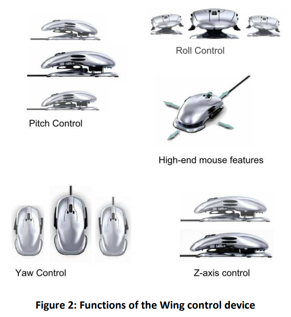
The Wing can be moved about on a work surface like with a normal mouse, but additionally, the upper body can be pitched, rolled and moved vertically relative to the lower body. The yaw bar, positioned between the upper and lower bodies can also be twisted.
 Remote Manipulation with the Wing Control Device

Contributed by | Worthington Sharpe Ltd.
Introduction
The Wing is a 6-axis control device that combines full three-dimensional (3D) control with the precision of a laser mouse.
It is designed to meet the control demands of Uninhabited Aerial Vehicles (UAVs or drones), Remotely Operated Vehicles (ROVs), remote manipulation, Computer Aided Design (CAD) software, Virtual Reality, and simulation or training software. Current uses include UAV control and CAD software. This document discusses how it could be used for teleoperation of manipulator arms.
Standard joysticks are typically used as manual input for teleoperation, yet this approach is neither particularly intuitive nor well suited to the task. Master-slave solutions, virtual reality gloves, or gesture control do offer an increased level of dexterity but they are complex, expensive, and often induce excessive operator fatigue.
An alternative approach is suggested here involving the Wing control device. The remote arm would be moved through a combination of direct manual control, and assisted teleoperation. The idea is to allow the operator to focus on the higher-level tasks, while utilising the Wing’s unique features to offer maximum control fidelity where it is needed.
Operating Principle
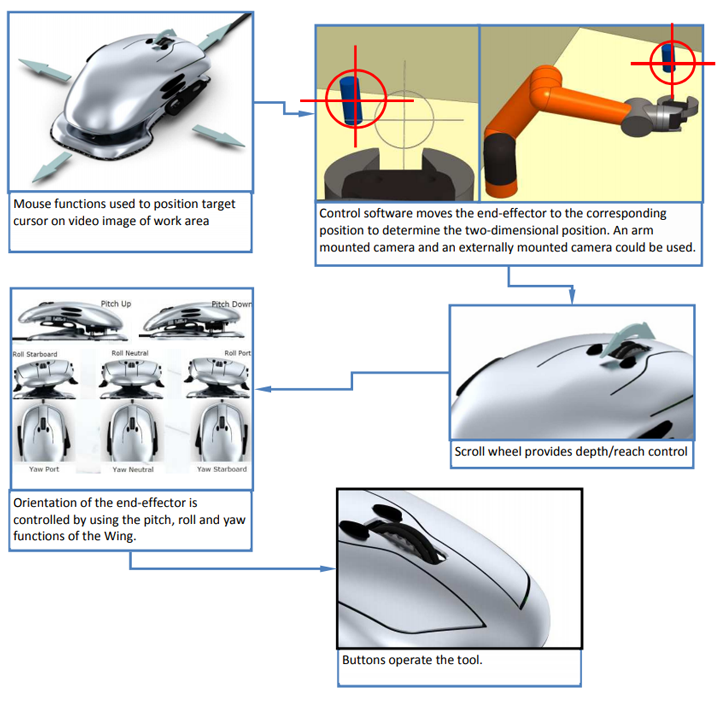
Operation with the Wing would involve positioning a target cross-hair on a video image of the work area by using the computer mouse functions that are central to the Wing’s design philosophy. The end-effector position would be moved using closed-loop control to match the two-dimensional position of the target. The scroll wheel or z-axis would be used for depth control. Simultaneously, the Wing’s pitch, roll and yaw functions would be used for controlling the end-effector orientation. Multiple buttons are available for gripper activation or other functions.
Full control of the arm with one hand means that the operator’s other hand is available to control vehicle movement, for operation of a second arm, manipulating the camera, or for other functions.
Computer Input and Remote Manipulation
A useful analogy can be made between the pointing and selection with a cursor on a computer screen, and positioning and grasping an object with a teleoperated manipulator arm.
It is the relative position of the target and the tool, or the target and cursor that is important in both cases. The objective is to move the cursor to a two-dimensional position on the computer screen, or to move the end-effector to a point in three-dimensional space. This comparison forms the basis for the philosophy behind this proposal and will be referred to throughout this document.
Integration and Separation
Another important consideration is associated with the separation of movements. In some cases, it is natural to integrate the different movement axes. For example, in order to move an object from a table to a shelf, a person would simply pick it up and move it in a combined tX-tY-tZ translation and rX-rY-rZ rotation action. Many practical tasks that require a high degree of precision can be seen to be a set of separated actions. Often the tool and workpiece are positioned approximately in an integrated 3D process, and then the final stages are carried out in two-dimensional or even one-dimensional stages. Threading a needle, cutting with a scalpel, drilling a hole or cutting with an angle grinder are common examples.
In comparable remote manipulation tasks, it is suggested that the human interface should allow the operator to control in both an integrated and separated manner. A purely freeform input device would only allow integrated movements by default.
Limitations of Current Solutions
Human-manipulator interaction currently involves a range of input devices ranging from standard joysticks, through to bespoke interfaces based on a master-slave principle. Both approaches lend themselves to a direct control relationship where the input is mapped directly to the robot movement. While the master-slave principle is more intuitive than joystick control, both methods require constant attention in order to be effective (You and Hauser, 2011). Many operators are highly skilled and make the current control interfaces appear optimally suited to the tasks. Notwithstanding the operator skill, these current systems of interaction between the human operator and the manipulator arm are limited in a number of ways, as is discussed below.
Joystick Control
A standard joystick might well be the most obvious way of controlling a robotic arm remotely where each joint is directly controlled by the different joystick axes. Two joysticks are typically used. Moving the joysticks in combination allows the tool to be moved to any point within the working envelope. The method has proven to be effective in practice but there is an argument that direct control is “slow, tedious, and unintuitive” (You and Hauser, 2011).
Master-Slave Control
Master-slave devices map the movement of a manually operated articulated arm directly to the movement of the robotic arm. Direct correlation between the control master and the slave arm mean that it is immediately intuitive, but any errors from the operator are also directly translated to the robot arm. As the master is usually smaller than the slave, the input needs to be scaled, and so any errors are magnified. Fatigue is also a concern as the operator needs to adopt what may be an uncomfortable posture as the master unit is carefully guided through each operation.
Computer Mouse Control
By expanding the analogy introduced earlier, it can be seen how a standard computer mouse could be used for 3-axis manipulator control. Mapping the mouse movement to Cartesian control of the end-effector could work in the same manner in which the mouse is mapped to an on-screen cursor, while the scroll wheel is used for z-axis control.
Non-linear scaling is commonly used with a mouse and is likely to also work well with manipulator control. Slow mouse movements would correspond to slower, more accurate movements of the manipulator, and fast movements would correspond to movements of increased magnitude.
There are examples of direct control using a mouse such as the uArm1 from uFactory. Industrial examples include the Externally Guided Motion2 (EGM) feature available in RobotWare from ABB, but there is not a great deal of information published about it that is readily available.
Assisted teleoperation with a computer mouse has also been demonstrated with some success (You and Hauser, 2011). They use a click-and-drag operation with the mouse and a range of assistance strategies for collisiona avoidance and path planning.
It is perhaps somewhat surprising that there are not more examples of computer mouse teleoperation. This might be explained by the extreme asymmetry (Hauser, 2012) between a 3-axis mouse (X-Y translation through movement on the desk, plus Z-translation through the scroll wheel), and a manipulator with six-degrees-of-freedom or more. Nevertheless, it would appear that the well documented factors (Balakrishnan, Baudel, Kurtenbach & Fitzmaurice, 1997) that have made the mouse extremely successful as a pointing device would apply equally to teleoperation.
1 https://www.youtube.com/watch?v=aJrsQIMTPBc
2 https://www.youtube.com/watch?v=3bywmHWcgdA
Physical form
The shape of the mouse along with the way it is operated on a flat horizontal surface means that the user is not restricted to any particular grip. It can be used with a relaxed grip for less critical movements, such as moving the end-effector in free-space, or a more concentrated grip for precision movements close to obstacles, or when operating the tool. Sometimes the importance of this factor is overlooked when considering control devices that need to be used for prolonged periods.
Stability
Any inadvertent shaking in the operator’s hand are damped due to the contact friction with the surface, allowing for much more precise movements than are possible with a freefloating device or gesture control. The mouse is also in a stable state where it is immediately ready to be used and does not have to be “disturbed” to acquire or release the device. Conversely, joysticks return to a central position when released and the cursor position on a touch-screen cannot be accurately re-acquired. Stability is increased further as resting the arm and part of the hand on the surface reduces fatigue and provides an anchor as a reference for delicate movements.
Relative vs. Absolute Mode
Input devices can either report their absolute measured position or their current position relative to some key point. Operation of absolute devices inherently tends to be more constrained as the movement range and scaling is fixed. The mouse is a relative device and so the zero-point can be changed and the amount of arm movement required to effectively use it can be very small. Thus, the user need not expend much effort when working with the mouse. Furthermore, the implicit clutching means it does not suffer from the “nulling problem” (Buxton, 1986); the action of lifting the mouse off the desk and replacing it to disengage and reengage is easily understood and users seem to find it quite natural.
Order of Control
Position control devices are found to be superior to rate control devices for common 3D tasks for computer interaction (Zhai, 2004). This is not particularly surprising, as it would be expected that to move an object from one point to another in a virtual sense would be best accomplished if the corresponding input involved movement from one point to another. If remote manipulation is considered to be an extension of computer interaction, then it would be expected that a similar relationship would also apply in this context.
Moving a pointer from a home position, to a target position, and back to a home position is a common action with both a computer interface and a remote manipulator. This type of reversible movement is easily accomplished with a mouse (or a master-slave device), due to users’ innate kinaesthetic sense of where their hand is. A reversal action is, cognitively speaking, more difficult to undertake with a rate controlled device such as a joystick, or Spacemouse3 , because the position of the user’s hand is not directly associated with the position of the cursor or the end-effector.
Device to Cursor Mapping
The default mapping of mouse motion to cursor motion is “natural”: moving the mouse forward moves the cursor up, and moving the mouse left moves the cursor to the left. This reduces the cognitive load imposed on the user since the relationship between the input and the output is simple. Most position control 3D devices have this feature, while force-sensing devices use more complicate device to cursor mappings that are less intuitive.
Familiarity
Mouse input is almost ubiquitous for desktop computer input and is immediately familiar to the majority of people. When comparing the movement of an on-screen cursor and a remote end-effector, it would be expected that untrained operators would have at least some aptitude when presented with a mouse-controlled remote manipulator.
3 http://www.3dconnexion.co.uk/
Alternative Approaches
There is an increasing amount of interest in non-traditional approaches to the human machine interface such as voice control, gesture recognition and brain-computer interfaces.
Mass-market products such as the Microsoft Kinect4 have probably increased the interest in solutions that do not involve a control device in the traditional sense. There is undoubtedly an appeal in what might be perceived as more futuristic systems, but the appeal for gaming does not necessarily translate to actual usability or applicability to teleoperation. A principal difficulty is in separating the intentional from the unintentional inputs, confounded by the fact that the input signal is generally noisy, low bandwidth and prone to systematic errors (You and Hauser, 2011).
Assisted teleoperation capabilities can help overcome some of the above limitations. Shifting the low level work-load to the control system reduces operator training time, decreases their cognitive load, and increases their situational awareness (Levine & Checka, 2010). However, assisted teleoperation relies on a high-level of computer intelligence in order to interpret the operator's intention and deduce the correct lower-level actions required. It certainly presents advantages, but the flexibility of the system is reduced due to the inevitable assumptions made by the system.
Devices such as the Spacemouse offer six-degrees of freedom and perform most effectively where there is a true requirement for integrated rate control in all directions. However, this metaphor does not apply to the examples presented in Section 2.3, or to a lot of other realworld manipulation or navigation tasks. For example, picking an object up to examine it is typically an integrated action, but it can be seen to most directly involve position control, not rate control.
4 https://developer.microsoft.com/en-us/windows/kinect/hardware
Wing Control Device
Since its original public demonstration in 1968, the computer mouse has changed very little. The sensing technology has improved, and the scroll wheel and extra buttons have been added, but its capabilities have not really advanced. The Wing was developed by Worthington Sharpe to add full three-dimensional control capabilities to the standard mouse.
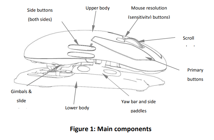
The Wing and its main components are shown in Figure 1. Springs centre the pitch, roll and yaw axes and are adjusted to virtually eliminate play in the joints. Hall-Effect sensors are used to detect the movements and a variable-resolution laser mouse sensor is fitted in the lower body to sense movements against a reference surface.
The Wing can be moved about on a work surface like with a normal mouse, but additionally, the upper body can be pitched, rolled and moved vertically relative to the lower body. The yaw bar, positioned between the upper and lower bodies can also be twisted. The functions are shown in Figure 2.
Principles of Operation
Several different manipulator arm control strategies would be possible with the Wing and it is likely that the proposed methodology would need to be adapted as the work progresses. An overview of what appears to be the most promising approach is presented here.
Control Strategy
To position the end-effector using the Wing, the mouse functions are used to position a target cursor on a video image of the work area, and the scroll-wheel or z-axis is used to determine height. Meanwhile, the pitch, roll and yaw functions are used to orientate the end-effector. The software would use inverse kinematics or another suitable control strategy to move the end-effector to match the target position. The target itself would be a purely graphical aid and so there would be no noticeable lag in its movement. It would give immediate feedback as to the intended motion of the manipulator and help the operator discern manipulator lag from any positional error. The principle is illustrated in
Interfacing with the Wing
Output from the Wing is a through a single USB port split into two separate USB endpoints that are recognised as two separate USB devices: a standard mouse, and a standard 4-axis joystick. The mouse movement could be related directly to the X-Y coordinates of the endeffector and the scroll-wheel directly to the Z coordinate. The Wing outputs pitch, roll and yaw as joystick channels, which could be mapped to rate-control, or position control of the end-effector orientation. The z-axis of the Wing is sent as the joystick “throttle” channel, but it would probably be better to concentrate on the other axes to begin with.
There are no known examples of the graphical target approach discussed here being used with a standard mouse and manipulator arm, but a more in-depth search might yield relevant results. Either way, as simpler way to start would be to set up a direct control interface between the Wing and the arm before progressing to more advanced control strategies.
Haptics
Haptic feedback is commonly used on master-slave type controllers to provide additional guidance to the operator during a remote manipulation task.
It would be possible to replace the springs on the pitch, roll and yaw axes with electric motors. Feedback torque from the motors would aid the operator when orienting the tool close to an obstacle, or for example, using the yaw axis to tighten a bolt. It might also be possible to use the Z-axis in conjunction with pitch, roll or yaw to give an indication of an X or Y translation.
Adding a translation force feedback on the X and Y axes is more difficult due to the nature of the Wing’s design; it is designed to be used like a computer mouse and so fixing it a base to provide a reaction for any force would likely be detrimental to its ease of use.
Designs that incorporate moving electromagnets inside a base unit have been developed (Akamatsu, M., Sato, S. and MacKenzie, 1994) but this approach would mean changing the Hall-Effect sensors currently on the pitch, roll and yaw axes.
Another option would be to use an arm that attaches to the Wing and that is generally compliant with the operator’s intended movement. When a reaction is experienced by the manipulator, this would be transmitted through the arm. A further approach might be to feedback a different response that corresponds to a translational reaction. For example, the yaw bar could be made to translate slightly in the X, Y and Z directions so that the operator feels the appropriate feedback in their fingers.
Limitations
Correlating the order of the input to the requirement is an important consideration that applies to computer interaction (Zhai, 1995) and there is no reason to think that it doesn’t also apply to remote manipulation. It has been discussed how the Wing’s X-Y movement correlates to the Cartesian movement of a manipulator arm. The orientation of the tool is however not as closely matched to the Wing’s pitch, roll and yaw axis movement when compared to the direct control offered by a master-slave system. How critical this is in practice is difficult to determine at this stage.
User perception is a major limitation and is likely to be something that is difficult to overcome with engineering solutions. The Wing looks and works like a computer mouse and this itself presents problems in that the mouse is sometimes considered to be outdated technology. It might be expected that operation of an expensive and complex manipulator arm should be with an appropriately expensive and complicated controller.
Conclusions and Further Work
This document is only intended as an introduction to the possibilities in using the Wing for remote manipulation. It is not expected that the proposed arrangement is ideal for every remote manipulation tasks. It is hoped however that the above discussion does at least present potential benefits that are worth exploring further. The next obvious next step is to demonstrate the feasibility with a suitable manipulator arm.
The division between the classes of remotely operated systems is arguably becoming blurred. A control system that can adapt to the different needs of every task is likely to be impractical, but the Wing and the Wing GCS present a novel combination of features that have potential in at least some of these situations.
Wing GCS
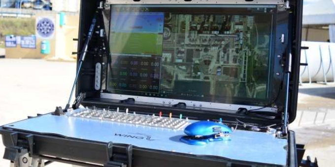
Further to the development of the Wing, Worthington Sharpe developed a Ground Control Station for UAVs, the “Wing GCS”. It was designed to provide a comprehensive set of ground based systems for UAVs. The Wing GCS would provide a suitable platform for integrating systems required for the control of manipulator arms. A copy of the brochure for the system describes it in more detail and is included in the Appendix.
References
- ABB. 2015. [Online] 2015. https://www.youtube.com/watch?v=3bywmHWcgdA.
- Balakrishnan, Baudel, Kurtenbach & Fitzmaurice. 1997. The Rockin’Mouse: Integral 3D Manipulation on a Plane. 1997.
- Card, English & Burr. 1978. Evaluation of Mouse, Rare-Controlled Isometric Joystick, Step Keys, and Text Keys for Text Selection on a CRT. Xerox Pllio Alto Research Center Palo, Aho, California. : s.n., 1978.
- Levine & Checka. 2010. Natural User Interface for Robot Task Assignment. Cambridge, MA : s.n., 2010.
- uFactory. 2016. [Online] 2016. https://www.youtube.com/watch?v=aJrsQIMTPBc.
- You and Hauser. 2011. Assisted Teleoperation Strategies for Aggressively Controlling a Robot Arm with 2D Input. 2011.
Appendix
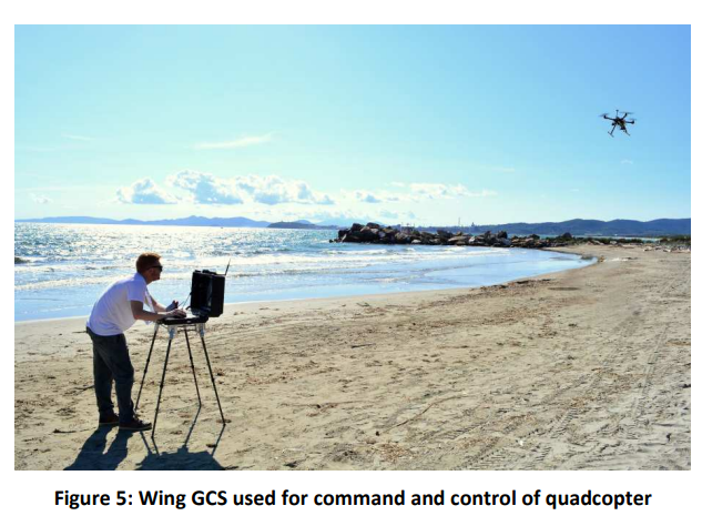
UAVs for commercial applications are often controlled from using a combination of a standard radio transmitter and separate laptop and telemetry system. The Wing GCS was designed to integrate all the required ground-based systems into a single unit and it is shown in Figure 4 and Figure 5.
.png)
The content & opinions in this article are the author’s and do not necessarily represent the views of RoboticsTomorrow
Featured Product

