Structured Light imaging is commonly used for machine vision because it can yield high resolution results. Some of the methods can be used effectively in moderate and high-speed applications.
What is Structured Light Imaging?
Contributed by | MoviMED
As the collective needs of our civilization become more sophisticated, the 2-dimensional imaging methods of the past impose limitations on what we can perceive and understand about the world around us. We live in a 3-dimensional world, and many application areas can benefit from 3-dimensional awareness.
Our “stereoscopic” eyes and cognitive processing abilities provide our 3-dimensional awareness, but stereovision isn’t the only way to extract 3-dimensional information. Several different 3D methods have been developed and applied to machine vision. One method that is rapidly growing in popularity (and utility) is Structured Light Imaging.
Structured Light Imaging
Structured Light Imaging captures the 3-dimensional topography of a surface using specific, (often modulating) patterns of light, and a 2D imaging camera. One well-known example of a structured light system is the Microsoft Kinect. Originally developed for gaming and consumer electronics, the Kinect – and other systems using similar technologies – are finding their way into a wide range of practical applications.
The concept is quite simple: a known pattern is projected onto a surface. When the camera views the pattern from one (or more) different perspectives, the surface features of the target distort the pattern, as shown in Figure 1. The direction and size of the pattern distortions are used to reconstruct the surface topography of the target object.
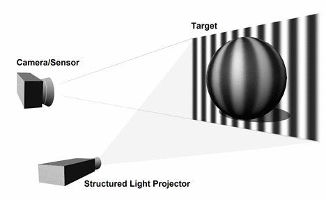
Figure 1: A regular striped pattern is projected onto the ball. The rounded surface of the ball distorts the stripes, and the distorted image is captured by a camera for analysis and object reconstruction.
In the example shown in Figure 1, a regular sine wave intensity pattern has been illustrated. This type of pattern is often used for the Phase Shift sequential projection method — just one of several methods that have been developed. Others include continuously varying rainbow patterns, grayscale or color stripe indexing, grid indexing (using pseudo random binary dots or 2D color coded dot arrays, for example), and others. In addition to these methods, there are also hybrid methods that combine more than one method to optimize the results for a particular surface or target.
Detailed discussions about the wide variety of methods is beyond the scope of this article. For the sake of this discussion, we will look only at the Phase Shift method in more detail.
Phase Shift
The Phase Shift method utilizes a set of grayscale images with the pixel intensities defined by a sine wave pattern as shown in Figure 2. Typically, three (or possibly more) images with a known phase shift between the images is used. The phase shifted patterns are projected sequentially onto the object, and after a phase unwrapping operation, the resulting difference images are compared with a reference plane to extract the surface features of the original object.
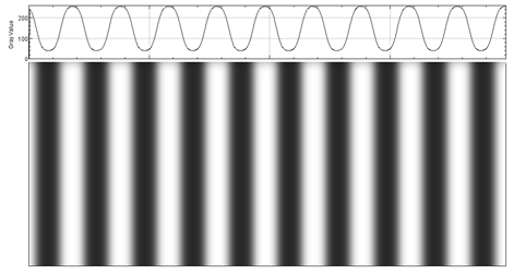
Figure 2: One of 3 sine wave pattern images of the type that are used for Phase Shift structured light projections.
Phase Shift Example

Figure 3: The scanning target – a plastic ball.
Now, let’s apply the Phase Shift method to a hypothetical example. Suppose we want to map the 3D surface of a plastic ball like the one shown in Figure 3.
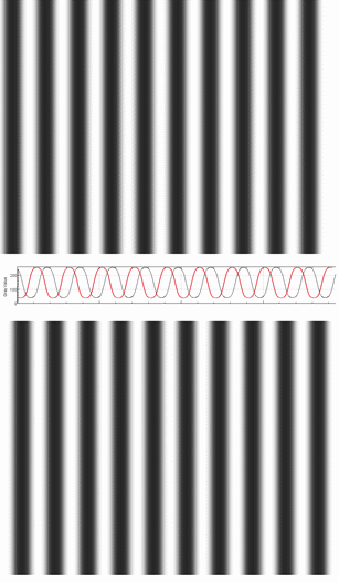
Figure 4: Phase shifted projection patterns.
Projection pattern images are prepared with a known phase shift between the images, as illustrated in Figure 4. (Note that 3 or more images are typically used. Only two are shown here to save space while still illustrating the point.)
After the projection patterns have been constructed, the patterns are sequentially projected onto the object, and images are captured. After unwrapping, a 3D surface map can be reconstructed, as illustrated in Figure 5.
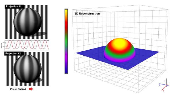
Figure 5: Phase shifted projections and the resulting 3D construction.
You may notice that only the front (or “upper”) half of the sphere is reconstructed on the right side of Figure 5. We are assuming that the camera has not been moved for this hypothetical example. It is important to understand that Structured Light imaging is not typically used to measure volumetric density (such as the MRI or CT scans used in medical imaging). It is more of a “surface mapping” method, in that it illuminates a surface, and maps the topographical variations of the surface rather than the volume of a body. Beginning with a planar surface as the reference, this method measures the deflection from this reference plane. Even though this method is only capable of capturing the deflection from a single plane in any given 2D view, a 3D mesh of the target’s entire 3D surface can be assembled by rotating the target through 360° and capturing multiple surface maps covering its entire surface.
As noted previously, the Microsoft Kinect is perhaps the most widely used structured light system. Rather than stripes or geometric patterns, the Kinect uses a projected IR dot pattern and an astigmatic lens (i.e. different focal lengths for the X and Y axes) to interpret object distance. The elongation, direction, and displacement of the projected dot pattern provides the depth cues, along with “depth from focus” and “depth from stereo” 3D imaging techniques. The Kinect is a powerful yet affordable 2-D and 3-D platform, offering 1280 x 1024 pixels resolution at a frame rate of 15 frames per second (fps).
Structured Light imaging is commonly used for machine vision because it can yield high resolution results. Some of the methods can be used effectively in moderate and high-speed applications. It allows for the acquisition of a multitude of samples simultaneously, and can be used to meet a wide range or practical challenges.
The content & opinions in this article are the author’s and do not necessarily represent the views of RoboticsTomorrow
Featured Product