Precision motion systems always exhibit some amount of positioning inaccuracy (or position error) due to various factors. These errors can be measured using external measurement devices, such as a laser interferometer...
How to Improve the Precision of Positioning Stages with ACS Dynamic Error Compensation
Contributed by | PI USA
1. Introduction
Precision motion systems always exhibit some amount of positioning inaccuracy (or position error) due to various factors. These errors can be measured using external measurement devices, such as a laser interferometer, and can then be corrected by changing the motion profile according to an error correction map. The ability to change the motion profile according to a preset correction map is called Dynamic Error Compensation and is a standard feature in all ACS SPiiPlus controllers used by PI.

A-824, ACS-based motion controller (Image: PI)
2. Terminology
Position accuracy (also called positioning error) is defined as the difference between the ideal target position to which the system was commanded to move (in the direction of travel) and the actual position as measured by an external metrology device, typically a laser interferometer.

Definition of target position, actual position, and position error in a linear stage. (Image: PI)
3. Error Sources
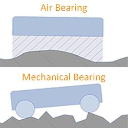
Position accuracy is influenced by imperfections in the position feedback system (such as a linear encoder), drive mechanism, guidance errors of the bearings, and deflection of the structure to which the stage is mounted. For more information, read also Straightness and Flatness of Air Bearings.
Position accuracy is also influenced by the location in space relative to the stage where the user’s payload or sensor is located. This location is called the “point of interest”, and the distance between this point and the stage is called an offset. Abbe error is the positioning error resulting from angular error motion of a stage’s moving part and the size of the offset. The greater the offset distance between the stage and the user’s point of interest, the greater the Abbe error. In the diagram shown below, the amount of pitch error from the stage combined with the length of the Abbe offset “h” will determine the Abbe error.

Abbe Error and Angular Errors (Image: PI)
4. Measuring Linear Positioning Accuracy
This test is performed with a retroreflector mounted to the stage’s moving table, with the optic located at the user’s point of interest. By doing this, the Abbe error is captured in the measurement.

Linear Interferometer Setup (Image: PI)
The interferometer beam splitter optic is placed at the end of the stage and is held stationary. The beam path is in the direction of motion.

Linear Interferometer Optical Schematic (Image: Renishaw)

Typical Accuracy Data Plot (Image: PI)
Under closed loop servo control, the stage is moved in fixed increments (typically 10mm – 50mm per step), and a measurement is taken at each point. The stage is moved through its full length of travel in both directions for multiple passes. The collected data is plotted and the overall accuracy is calculated. The accuracy and repeatability results are typically reported in microns.
5. Measuring Rotary Positioning Accuracy

Rotary Position Error Laser Interferometer Optical Schematic (Image: Renishaw)
This test is performed using the Renishaw XR20-W rotary axis calibrator mounted to the rotating stage table. The XR20-W consists of an integrated angular retroreflector mounted on a precision servo-controlled axis. The angular position of this axis, and the optics relative to the main body housing, is controlled by a very high accuracy encoder system with the scale directly machined onto the main bearing. The angular interferometer optic is placed at the end of the stage and is held stationary. The angular optic setup creates two beam paths. As the stage rotates, the XR20-W counter-rotates by the same amount. The angular error is calculated based residual rotation measures by the laser.
In the same way that the linear accuracy data is collected, the stage is moved in fixed increments (typically 5° - 30° per step), and a measurement is taken at each point. The stage is moved through its full range of travel, in both directions, for multiple passes. The data that is collected is plotted and the overall errors are calculated. The results are typically reported in arc-seconds or microradians.

Rotary Axis Calibrator (Image: Renishaw)

Typical Rotary Positioning Accuracy Plot (Image: PI)
6. Correcting Position Errors using Dynamic Error Compensation
Using data from the position error measurements, a correction table can be generated and loaded into the ACS motion controller. The errors are corrected by changing the motion profile on the fly, according to the correction map, via a controller feature called Dynamic Error Compensation.

Example: Improved XY-stage position accuracy after ACS dynamic error compensation.
Dynamic Error Compensation constantly provides a corrected trajectory to the stage. This means the error corrections are made while the stage is in motion, not just at the end of a move. True position tracking during motion is achieved in this way. The controller also interpolates between the discreet points provided in the correction table.
7. Results
Shown below are typical position error plots for PIglide air bearing stages taken before and after the implementation of Dynamic Error Compensation using an ACS SPiiPlus Motion Controller. The final results that can be obtained with error compensation are limited only by the repeatability performance of the stage.
7.1. PIglide A-123.500A1 Linear Air Bearing Stage


Before Dynamic Error Compensation (Image: PI)

After Dynamic Error Compensation (Image: PI)
7.2. PIglide A-623.050A1 Rotary Air Bearing Stage


The content & opinions in this article are the author’s and do not necessarily represent the views of RoboticsTomorrow

PI USA (Physik Instrumente)
PI is a privately held company that designs and manufactures world-class precision motion and automation systems including air bearings, hexapods and piezo drives at locations in North America, Europe, and Asia. The company was founded 5 decades ago and today employs more than 1700 people worldwide. PI's customers are leaders in high-tech industries and research institutes in fields such as photonics, life-sciences, semiconductors and aerospace.
![]()
![]()
![]()
Other Articles
High-Throughput PIC Production Needs Precision Alignment Equipment for Photonics Arrays, Fibers, Lenses
Fast Hexapod Improves Aircraft Manufacturing Process
Fiber Alignment and Photonic Chip Test & Assembly Just Got Easier
More about PI USA (Physik Instrumente)
Featured Product