The terms accuracy and repeatability are often used interchangeably. However, accuracy is not possible without repeatability, but repeatability is achievable without accuracy. There are other errors, too, non-linearity errors, and linearity errors caused by thermal effects.
 Why Repeatability and Accuracy are Different in Motion and Positioning Related Applications
Contributed by | PI USA
The terms accuracy and repeatability are often used interchangeably. However, accuracy is not possible without repeatability, but repeatability is achievable without accuracy. There are other errors, too, non-linearity errors, and linearity errors caused by thermal effects.
Here’s a closer look at the differences and information on what errors can be eliminated by compensation techniques.
Repeatability errors (or lack thereof) allow the motion system to return to the same point in space repeatedly and when approached from any direction; this is called bi-directional repeatability. This type of error cannot be compensated or calibrated, since it is by nature non-repeatable and therefore non-predictable. PI focuses on addressing this type of error when designing and building a motion system. The more repeatable a system can be built, the better the remaining errors can be dealt with through compensation methods.
.png)
In order to get reliable data, high quality metrology equipment is required. For accurate linear measurements, laser interferometers are employed.
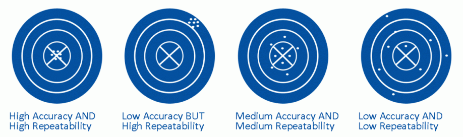
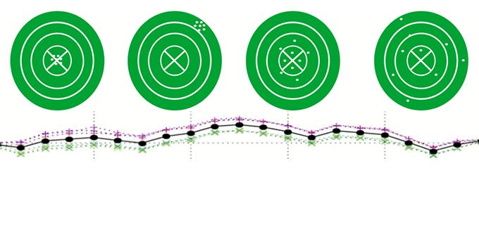
A graphic representation of accuracy and repeatability
Non-linear errors are accuracy error motions that do not follow a straight line as the stage moves through its travel range. An example of an accuracy plot for a linear stage is shown below:
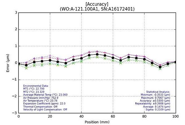
Positioning stage accuracy plot. The error (commanded position minus the interferometer measured actual position) is shown on the Y axis and stage position on the X axis. The black line represents the average of multiple test runs, the colored lines are the actual runs. The spread of the data at any one stage location represents the repeatability.
After we perform metrology on a system, we apply error compensation in the motion controller to calibrate (or correct) the repeatable positioning error of the system. If done well, the black line in the plot becomes a flat line at zero.
Finally, there are linear errors. These are errors that are most commonly caused by thermal expansion effects. As the stage structure and encoders expand and contract with temperature changes, the flat straight line in the plot above becomes a diagonal line. However, since the error is linear, it can easily be addressed by applying a scaling factor to either the motion controller or in a machine vision system.
If this behavior is a concern for the respective application, a calibration routine can be built into the machine, where the stage is moved to a fixed point in space to look at a fiducial, then is moved to another 2 or 3 fiducials. The errors between the expected locations and measured locations are then calculated. The scale factor can then be adjusted based on these measurements. Such calibrations are usually done periodically, either at a fixed time interval (i.e. every 10 minutes) or in a process interval (i.e. before the start of each batch). Any changes in machine accuracy due to thermal effects are taken care of in this way.
It is not practical, except in very extreme (and costly) cases, to try and build a motion system that holds its accuracy over a wide temperature range without using a calibration routine such as described above.
The content & opinions in this article are the author’s and do not necessarily represent the views of RoboticsTomorrow

PI USA (Physik Instrumente)
PI is a privately held company that designs and manufactures world-class precision motion and automation systems including air bearings, hexapods and piezo drives at locations in North America, Europe, and Asia. The company was founded 5 decades ago and today employs more than 1700 people worldwide. PI's customers are leaders in high-tech industries and research institutes in fields such as photonics, life-sciences, semiconductors and aerospace.
![]()
![]()
![]()
Other Articles
High-Throughput PIC Production Needs Precision Alignment Equipment for Photonics Arrays, Fibers, Lenses
Fast Hexapod Improves Aircraft Manufacturing Process
Fiber Alignment and Photonic Chip Test & Assembly Just Got Easier
More about PI USA (Physik Instrumente)
Featured Product