The design and functionality of a DC motor controller depend on the characteristics of the motor and the electronic system it powers. Using the example of a brushed DC motor controller, we'll consider its operating principles and circuit design.
Design and Operation Features of a BDC Motor Controller
Andrey Solovev, CTO and co-founder | Integra Sources
A motor controller can play an essential role in the performance of electrical motors, including those powered by direct current (DC). DC motors first came into use in the 19th century, and they have been widespread ever since. Various types of DC motors can have both similarities and differences in their control systems. This article gives an outline of DC motor types and applications and focuses on brushed DC motors and their controllers.
Brief Introduction to DC motors
DC motor types include brushed, brushless, stepper, and servo motors. The last type is a DC motor configuration or mechanism used for angular positioning. The construction of DC motors comprises a rotor (or armature) that revolves under the magnetic field and a stator with either windings or permanent magnets. To run continuously, DC motors need to create a variable magnetic field.
For example, brushed DC (BDC) motors achieve this by using a mechanical commutator with carbon brushes, while brushless DC (BLDC) motors use an electronic controller to switch the polarity.

DC motor types
The absence of a commutator with brushes makes a BLDC motor more wear-resistant and fail-safe. It is used widely in industrial electronics and electric transport, such as cars, scooters, bikes, and drones. Stepper motors enable electronic devices to fix their positions with high accuracy, which is essential for robots and CNC machines.
Although a brushed DC motor looks like a vintage when compared to its brushless counterpart, a lot of electronics manufacturers, engineers, and users haven’t yet brushed them aside. You can find them in a number of consumer electronics, including:
- home appliances;
- toys;
- automotive electronics.
There are at least two important arguments regarding the use of a brushed motor, namely its simplicity and low cost. A brushed DC motor has a simpler construction, it is easy to implement, run, and control. You don’t need sophisticated electronics and a big budget to build a BDC motor controller. That is why we’ve decided to emphasize this type of motor in this article.
Brushed DC Motors and Their Controllers
As mentioned earlier, brushed DC motors have a mechanical commutator with brushes. It connects the rotor to a direct current source and switches the current polarity. As a result, the magnetic field generated around the rotor’s windings changes its polarity too.
The rotor moves towards the oppositely charged part of the stator that has various configurations. Depending on these configurations, BDC motors are classified as follows:
-
Permanent magnet BDC motors
The motor’s stator has permanent magnets. Such motors have improved speed control and high torque at the beginning, but there is a certain torque limit that they cannot exceed. -
Series BDC motors
The motor’s stator has windings connected in series to the rotor. These motors have high torque when the motor starts, but they have poor speed control. -
Shunt BDC motors
The motor’s stator has windings connected in parallel to the rotor. The motor provides increased speed control, including reverse rotation. -
Compound BDC motors
These motors have a wound stator and combine features of both series and shunt motors.
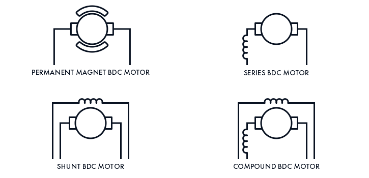
BDC motor types
Unlike with a brushless DC motor, a controller of a brushed motor doesn’t engage in the commutation process. A BDC motor controller regulates the motor’s speed, torque, rotational direction, and other parameters depending on requirements. The regulation of these parameters is closely tied to the control of the current and voltage supplied to the motor. There are two options used to accomplish this.
A linear voltage regulator uses a transistor regulator to inject voltage into the motor and keep its level stable. With that, the output voltage is always constant, so as to maintain it at the appropriate level, the input voltage must be even higher all the time. This often leads to power dissipation.
A linear regulator is simple, cheap, and works well for low-power applications. However, it is rarely found in modern electrical motors because of its poor efficiency. To consume electrical power more effectively, a BDC motor controller uses a switching voltage regulator that makes it possible to supply voltage in pulses.
This method is called pulse-width modulation (PWM). It allows the controller to divide the input power into active signals, or pulses, when the power is on, and passive signals when the power is off. Thus, a pulse period includes one cycle of switching power on and off. A PWM BDC motor controller changes duty cycles (the ratio of the pulse to the pulse period) and supplies voltage to the extent necessary for increasing or decreasing the motor’s speed.
Considering its widespread use, let’s take a look at the circuit design of a brushed DC motor controller with a switching regulator.
BDC Motor Controller Circuit
Most modern BDC motor controller circuits have an arrangement of the so-called H-bridge. An H-bridge circuit comprises four switches that supply voltage and rotate the motor when turned on diagonally. Gate drivers receive signals from a microcontroller (MCU); after that, they close or open the switches supplying the desired level of voltage. You can use different types of transistors for the switches, including:
- Power MOSFET
- GaN
- IGBT
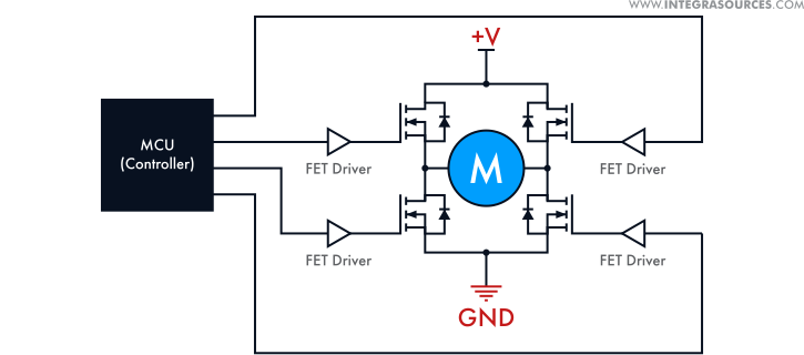
H-bridge BDC motor controller circuit
Depending on the requirements, you can choose between discrete components and an H-bridge integrated circuit (IC). The same goes for the gate drivers that can be either discrete or have built-in transistors. The gate driver IC is a developer-friendly option with an important drawback - it is not customizable. So, if you’re planning to create a bespoke controller for a high-power application, it is better to build it from discrete components.
A BDC motor controller circuit can be of varying complexity. For example, a non-feedback or open-loop controller is easier to design since it doesn’t require any feedback mechanisms. If a controller needs to monitor the motor’s state and react to any fluctuations in its behavior, there must be a feedback or closed-loop control system inside.
For example, to control the speed, you can use a Hall-effect sensor or a rotary encoder installed on the motor. These sensors convert the motor’s revolutions into digital signals read by the closed-loop controller.
The BDC motor controller design can have various options and nuances that depend on the controller’s functionality. In this article, we’d like to focus on braking as one of the important functions performed by modern DC motor controllers.
Braking a BDC Motor
You can use several methods to stop or break a brushed DC motor. These methods can be different for motors with various stator configurations. Here, we’ll view the braking of a permanent magnet BDC motor, which is widely used because of its small size, lightweight construction, and high efficiency. So, there are three basic and one additional way to stop the motor:
-
dynamic braking (a motor operates as a generator with a rotor short circuit to load);
-
regenerative braking (a special case of dynamic braking most commonly used in self-contained power supply systems);
-
plugging or reverse-current braking (the current is supplied in opposite polarity to the polarity of the motor operating in the generator mode);
-
alternative current (AC) supply (an additional braking method).
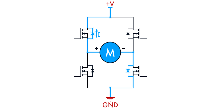
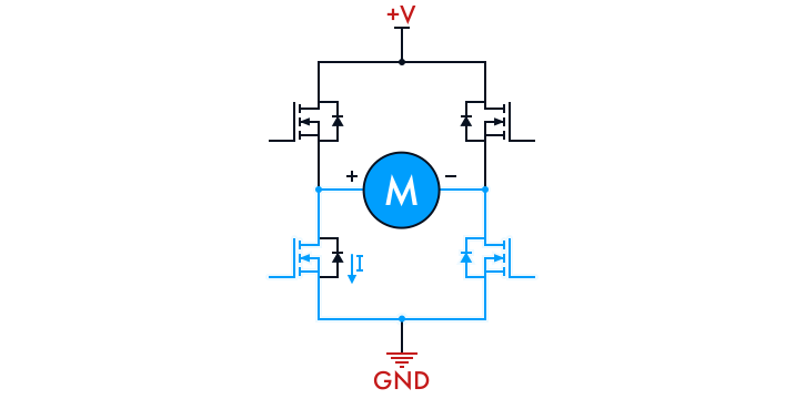
The simplest and smoothest way of braking is regenerative braking. If all four transistors of an H-bridge are closed, the motor will be connected to the power supply with the help of the transistors’ protective diodes. Thus, regardless of the motor’s rotational direction, the voltage and current will flow to the power supply with the correct polarity.
If the electromotive force (EMF) generated by the motor exceeds the supplied voltage with the voltage drop on the diodes, the motor will deliver power to the power supply and start braking.
This method is effective if the motor’s rotational rate is high enough. To reduce the power loss on the diodes, you can open the corresponding pairs of transistors placed on the H-bridge in a diagonal pattern. But you should consider the decrease in the rotational rate to prevent the EMF generated by the motor from dropping to the voltage level of the power system. In addition, you should know the direction of the motor’s rotation.
Regenerative braking
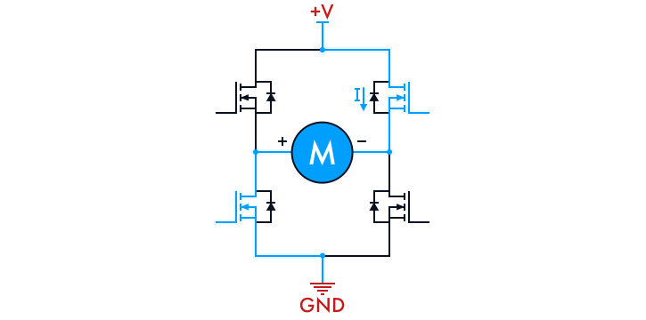
You can implement dynamic braking by switching (turning on and off) either two low-side or two high-side H-bridge transistors simultaneously. However, this is not always possible because of the schematic design of the H-bridge gate driver.
If you know the direction of the motor’s rotation, you can open only one switch, and the current will flow through the protective diode in the second transistor. By applying a PWM signal to the switches, you can control the braking that will be proportional to the duty cycle.
Dynamic braking
To implement plugging or reverse-current braking, it’s important to know the rotational direction of the motor or the polarity of the EMF it generates. Thus, you can apply the reverse voltage and create the maximum braking force. It’s also necessary to know the motor’s rotational speed or monitor the current flowing through the motor to stop it at the right time and prevent its reverse rotation. You can combine this method with the PWM control to modify the braking force.
Reverse-current braking
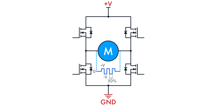
An additional way of braking is the supply of alternating current or voltage, which can be regarded as a simplified version of reverse-current braking. As we know, a permanent magnet BDC motor can’t run on AC power. In such a mode, a rotor will only vibrate without rotating. However, it will still create a braking force.
As we have already mentioned, an H-bridge circuit allows a controller to switch transistors diagonally. With a 50% duty cycle, you can apply alternating voltage (if you make a differential measurement of the motor’s voltage) to the motor that will create a braking force. You can regulate this force by decreasing or increasing the dead time of the PWM signals for the H-bridge.
Supply of alternating current or voltage
All the above braking methods have an apparent drawback. The EMF produced by the motor in the generator mode can exceed the permissible limit of the power supply, which may lead to the failure of the onboard electronics.
An important feature of these methods is that the controller and the wires will dissipate the power generated by the motor. That is why when implementing any of the methods, you should estimate the allowable operating modes of the circuit components. For example, semiconductors (transistor switches) may not stand a voltage surge, a strong current pulse, or they may simply burn out during the prolonged braking.
You should also pay attention to the controller’s schematic design because some braking modes put additional requirements on this design. For example, if your controller can open the H-bridge switches only in a diagonal pattern, you won’t be able to implement dynamic braking. And if you don’t know the direction of the motor’s rotation, you’ll be unable to use reverse-current braking.
Thus, before building a controller, you should have clear technical specifications describing the functionality of the device and its implementation at both hardware and software levels. In our article on DC motor controllers, we have specified various design principles and circuit examples and shared our personal experience with brushed motors.
The content & opinions in this article are the author’s and do not necessarily represent the views of RoboticsTomorrow
Featured Product