Finding and implementing the perfect end-effector system is reliant on the user giving due consideration to four critical areas. Only when complete understanding of the needs in these four realms is acquired can an educated end-effector choice be made.
 4 Critical Considerations When Selecting a Robotic End-Effector System

Benjamin Pauzus, Jr. | DESTACO
The robotics industry has been undergoing a noticeable demographic shift in recent years. Whereas the preponderance of robotics usage had traditionally been in conjunction with industrial applications, there has been significant growth in the use of non-traditional robots. The most popular are customer-service robots, personal-assistant robots, unmanned aerial vehicles (or drones) and so-called “driverless” vehicles. Despite that shifting landscape, industrial robots will remain a critical part of a market that some expect to reach $500 billion in sales revenue by 2025.
One industry, for example, that will continue to rely extensively on robots and automation is automobile manufacturing. This industry was one of the first to embrace robotics/automation as a way to enhance and optimize manufacturing times and schedules. Others that will continue to be indebted to the work of automation include the packaging, pharmaceutical and aerospace industries.
That being said, there are still manufacturers in these industries and many others who can further enhance their experience with automation applications. Two that readily come to mind are the metal-stamping and metal-assembly industries.
In the metal-stamping industry, there are a number of commonly used styles of press lines on which parts are formed, including:
-
Progressive: Progressive press lines are used to run smaller parts that do not require automation or end of arm tooling (EOAT) to move the part from die to die as they progress down the line. An EOAT acts as the robot’s “hand” as a part is either held in place or moved to the next station in a manufacturing process.
-
Transfer: These types of press lines feature three-axis transfer rails that transfer the part from die to die and are powered either mechanically or via a servo motor. Mechanically powered transfer lines have a fixed motion relative to the press’s Ram timing, while servo-powered transfer allows for the motion to be programmed and ultimately optimized for the best possible throughput or stroke per minute.
-
Tandem: The tandem style features a series of presses, usually between four and seven, arranged in a row. The part-transfer process in a tandem press is usually configured as a three-axis pick-and-place system or through a six-axis robot that is situated between each individual press.
No matter the type of press line that is used, keep in mind that stamped parts are not always completed parts. In many instances, the stamping will need to be welded or assembled before it becomes a finished part. These requirements transform the metal-stamped part into a metal-assembly process. In this case, robots and robotic EOAT play an important role in ensuring the efficiency and accuracy of the metal-assembly process.
Now that we have identified and defined the different types of press lines that are available, the remainder of this article will focus on the four critical considerations that must be made in order to optimize automation or robot-dependent press and body shop operations. It will also offer direction on how to choose the best automation tooling or end effector for the operating conditions.
In The Beginning…
Imagine joining a 100-meter dash from a standing start at the 25-meter mark as all of the other runners are racing past. Or entering the Indy 500 after the rest of the field has already driven 20 laps. In those conditions, it will be virtually impossible to win the race. Too often, that is the position in which the suppliers of the end effectors for a new workholding or pick-and-place system find themselves.
A traditional die design process asks the end user to work initially with the die maker in order to create the die designs that will be used to make the required parts. After several review-and-revision stages, the die will be approved by the end-user and CAD drawings of the dies will be created. At this point, the supplier of the automation tooling will be selected and receive the agreed-upon die data. Using this die-date information, the tooling supplier will create a tooling design and working simulation of the automation tooling. Upon review of the user, a Corrective Actions Report (CAR) will be fashioned that makes note of any clearance or clash issues that occurred during the simulation. The CAR will be sent to the die manufacture, who will work to resolve any clearance or clash issues before shipping the dies.
To be fair, the reason for this mindset becomes readily apparent when you realize that a fully designed and functional die set can cost upwards of $200,000, while the cost for the end effectors will generally be less than 10% of that upfront cost. While it’s understandable that the system designer and end user will devote more attention to the more expensive component, all parts in the system – no matter how big or small, expensive or inexpensive – must work in complete harmony in order to create a fully functional and reliable system. Therefore, if the automation-tooling supplier was involved earlier in the design process, costly time and rework of the die modifications can be avoided.
So, the end-effector supplier will typically be allowed to merge into the design process upon receipt of a process sheet with suggested grab and/or grip points where the Finger Tooling or EOAT will be needed. In trying to catch up, the supplier of end effectors will design the system’s touch points, simulate the motions needed (clamping, lifting, pitch, unclamp, etc.) and work with the die manufacturer to ensure that the end effectors work harmoniously with the already-produced die. The die manufacturer will determine if the dies and end effectors are compatible and able to deliver what the end user needs. If modifications are needed, a corrective-action report will be created. When all modifications are made, simulations will be performed to see if the system can perform as expected.
From a macro perspective, with all of the necessary back and forth between the die and end-effector constituencies, it seems that it would behoove the end user and system designer to incorporate the EOAT supplier at the outset of the design process. In fact, thanks to advances in digital-design capabilities and the openness of forward-thinking manufacturers to reconsider the traditional ways of doing things, a “one for all, all for one” mindset regarding robot-reliant workholding and pick-and-place system design is beginning to establish a foothold.
The 4 Things To Consider
Finding and implementing the perfect end-effector system is reliant on the user giving due consideration to four critical areas. Only when complete understanding of the needs in these four realms is acquired can an educated end-effector choice be made.
1. Operating Environment
There are two basic industrial-manufacturing environments where robotic-reliant part-handling systems will be used. They are:
-
Press Shop: In general, the press shop is where traditional part-stamping processes are performed, though the definition of the press shop has been evolving in recent years. Old-school setups have what is known as a “transfer press” operation, which is a linear operation that relies on non-robotic automation. However, more press shops are beginning to incorporate “tandem” lines in their facilities, which use robots to perform their various functions. Therefore, the end effectors in a tandem line need to be compatible for use with robots.
-
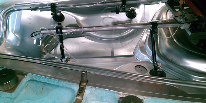
Body Shop: In the body shop, parts that have already been stamped are married together via welding, gluing, etc. The body shop is a robot-reliant facility, with modular end-effector systems developed to meet the needs of the specific applications, most of which require precise positioning and holding of parts.
2. Operating Parameters
Whether the end-effector system is used in a press shop or body shop, there are three major operating parameters that should be assessed and quantified before the best end effector can be selected. They are:
-
Cycle Time: In the Press Room you will find cycle time measured in strokes per minute (spm), which is the number of parts stamped per minute. In the Body Shop, it is the movement or operations the end-effector system can perform to complete a part. For example, a typical transfer press can perform at a rate of 15-22 spm. The efficiency of the system design can help improve the spm rate. Also, advances in digital-design and simulation capabilities can now allow die and end-effector designers to perform interference studies, which can point out potential bottlenecks in the part-moving process. These bottlenecks can then be designed out of the system before it becomes active, which helps optimize its spm abilities.
-
Weight: The weight of the parts that will be moved plays a huge role in determining the type of end effectors that can be used. It is important that the designer of the EOAT, or transfer fingers, understands that the tooling needs to be designed as robust and as light as possible, so it can perform reliably, with no drops, vibrations or misplacements, and be able to handle many thousands of transfer cycles without fatiguing or breaking down.
-
Reach: How far the end-of-arm tools will have to extend to perform their required task will also determine which end-effector solution is best for the job. It’s best when the robot or automation can reach or travel as much of the required distance as possible. The idea here is to limit the amount of offset load and/or weight of the EOAT or transfer finger. Keeping the EOAT or transfer finger as small (minimum offset load) as possible will help reduce the deflection, resulting in a better automation cadence and more efficient throughput.
3. Which End Effector?
Now that we know the types of operating environment and operational parameters the robot-driven end-effector system will encounter, it’s time to consider the construction methods of the end-effector types that can be deployed.
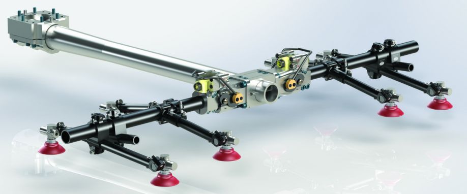
There are basically two options, the first of which is Modular Tooling, which is gaining in usage and acceptance. This option requires less design time because the end effector can be built from a standard library of CAD components. This results in better design consistency, along with offering more flexibility if changes in product design are ever needed. By using a standard design and components, Modular Tooling requires fewer custom parts, which leads to reduced assembly time. The finished product will also have less overall weight with reduced startup times and quicker recovery if a crash should occur during operation.
The second end-effector design option is the more traditional Welded Construction. While this method brings with it high levels of durability and reliability, its design and operational characteristics can pale in comparison in many ways to those offered by Modular Tooling. Since this method has fewer standard components in a CAD library it can take longer to design the end effector. This also makes it more difficult to factor in or predict future design changes, while variations may also exist among design teams. Building a welded end effector can also require more customized parts, which can result in longer assembly times. The end result will be a heavier part and corresponding longer startup times. Crash-recovery time can also be longer with a welded part.
4. Ancillary Components
Finally, there are ancillary components that can be used with the end-effector system to consider. These are:
-
Vacuum Cups and Magnets: These are the components that actually contact the part or finished product that needs to be held or moved. Vacuum cups are most popular for this task and are available in a variety of sizes, shapes, treads, flexibility levels, materials of construction – most commonly rubber, though polyurethane is making some headway in the market – and connections to vacuum sources, usually a venturi. Magnets are usually used in applications where there is insufficient surface area to reliably and safely pick and place the part with vacuum cups.
-
Grippers/Powerclamps: Sheet-metal grippers or powerclamps can be utilized to hold the parts. Lightweight sheet-metal grippers are ideal for use in part-handling applications in a press shop. The gripper’s internal mechanism prevents it from opening when air pressure is lost. Sheet-metal grippers come in an array of grip styles with multiple contact-point options. When part handling in the Body Shop, powerclamps are often used. They feature an enclosed pneumatic toggle-lock, and power clamps with integrated open/close sensing can secure a part even when air pressure is lost.
-
Venturis: Venturis have gained global acceptance as the main source of supplying vacuum to an end-effector system’s vacuum cups. Traditional systems operate with two lines, one that creates the vacuum that allows the retrieval of parts and a second that adds air to the cup, which allows the part to drop. However, new single-line venturis are gaining in popularity. Single-line venturis require 50% less air, which reduces operating costs, and with only one air line that needs to be serviced, maintenance costs are also reduced.
Conclusion
Though the overall market demographics may be shifting, the use of robotics in workholding and pick-and-place applications in industrial manufacturing will not be going the way of the dinosaurs anytime soon. For industrial manufacturers who are using automation/robotics in their press shop and body shop operations, it is extremely important that they design and deploy an automation tooling/end-effector system that is compatible with the automation/robotics being used. The best way to do this is by involving automation tooling/EOAT suppliers in the design process from the start, knowing all of the variables and options that are in play, using the latest digital-design technologies and working hand-in-hand with all parties.
About Benjamin Pauzus, Jr.
Benjamin Pauzus, Jr. works in Business Development, End Effectors for DESTACO, Auburn Hills, MI. He can be reached at bpauzus@destaco.com. Founded in 1915 as the Detroit Stamping Company, DESTACO is the industry’s leading global supplier of precision movement, positioning and control solutions in industrial automation. The DESTACO family of products consists of industry-leading brands such as DESTACO Manual Clamps, Power Clamps, and End Effectors; Camco™ and Ferguson™ Indexers; Robohand™ Grippers; and CRL™ Manipulators and Transfer Ports. The company operates globally through approximately 800 employees across 13 locations, and is part of Dover Corporation. For more information, please visit destaco.com.
The content & opinions in this article are the author’s and do not necessarily represent the views of RoboticsTomorrow

DESTACO
DESTACO is now the worldwide leader in the innovation, design, manufacture and support of clamping, gripping, transferring, indexing and robotic tooling solutions for workplace and automation needs.
Other Articles
Automate 2025 Q&A with DESTACO
DESTACO Smart Electric Product Line of Clamps and Guides
Talking AUTOMATE 2024 with DESTACO
More about DESTACO
Comments (0)
This post does not have any comments. Be the first to leave a comment below.
Featured Product


