The latest wireless charging solutions use techniques based on the principle of electromagnetic induction. When an alternating current is passed through an induction coil on the transmitter side, an oscillating magnetic field is created.
2022 Top Article - Wireless Charging Enables Industry 4.0 Implementation with Mobile Robots
Pramit Nandy And Vijay Bapu | Microchip Technology, Inc.
The manufacturing industry has been evolving for over 200 years now. Industry 4.0 is the fourth industrial revolution concentrating on interconnectivity, automation, machine learning, and real-time data processing. As various manufacturing industries are marching towards Industry 4.0, to stay competitive and reduce manufacturing costs, manufacturers are putting more equipment and less people in factories.
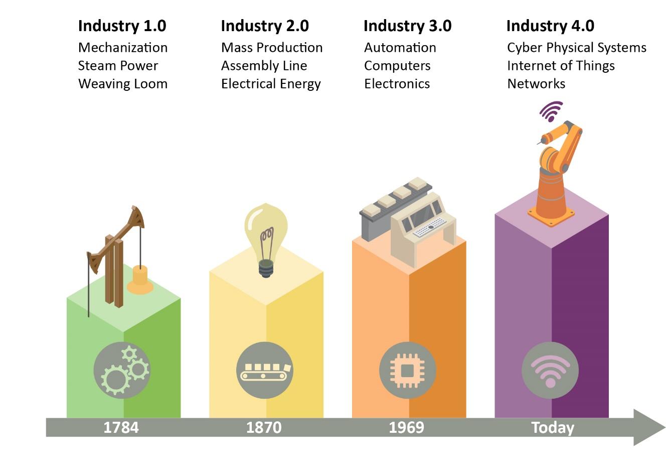
Manufacturing industry evolution
Manufacturers are investing heavily in advanced mobile robotics in their factories (i.e., Amazon delivery warehouses, assembly lines) and warehouses for doing the lion’s share of the building, assembling and transporting of material. However, these mobile robots must be charged regularly which is an increasing challenge for industrial factories. There have now been some improvements in the wireless charging space that are making these robots more flexible, which has boosted the manufacturing capacity and efficiency of factories. With the right combination of component selection, coil design and board layout, wireless charging is becoming a game changer for the manufacturing industry and is impacting the whole economy.
How Wireless Charging Works
The latest wireless charging solutions use techniques based on the principle of electromagnetic induction. When an alternating current is passed through an induction coil on the transmitter side, an oscillating magnetic field is created. When this oscillating magnetic field couples with an induction coil on the receiver side, an alternating electric current is produced in the receiver side coil (see Figure 2).
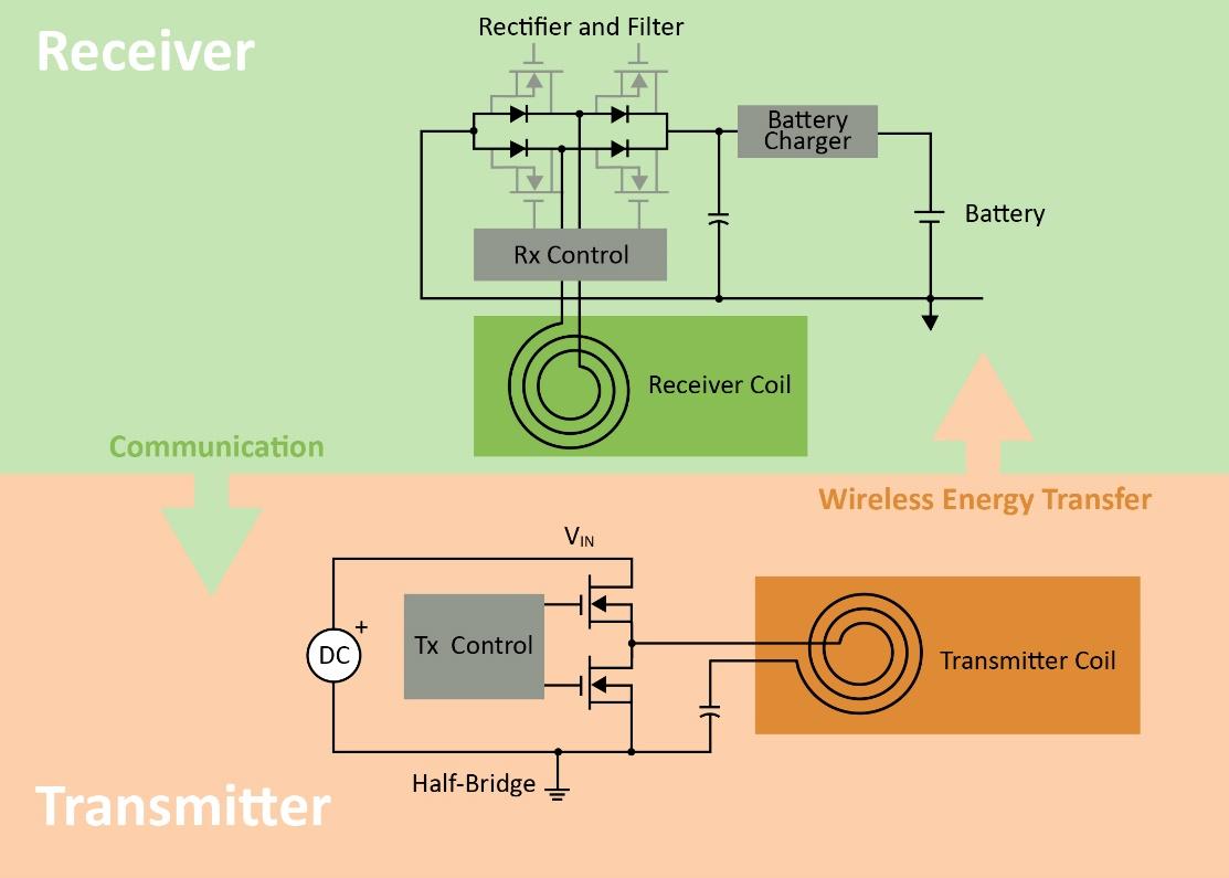
With inductive wireless charging, an alternating electric current is produced in the wireless charging solution’s receiver side coil.
Wireless charging systems require a number of components including the transmitter coil, tuning capacitors, a coil drive and a receiver coil. Other components include diode rectifiers, a DC-DC converter, transmitter and receiver control circuitry and algorithms, and a battery charging circuit.
In the example shown below, electromagnetic induction enables the wireless charging systems to transfer energy from a charging source pad installed on the factory floor to a receiving pad installed on the mobile robot.

Wireless charging of mobile robots on a factory floor
Benefits of Wireless Charging on the Factory Floor
Modern wireless charging systems with increased efficiency and cost-optimized components have proven to be a game changer in a factory setup for a number of reasons. First, they improve productivity and reduce manufacturing costs in a variety of ways. They enable continuous operation with opportunity charging (i.e., using idle time to charge), and reduce investment since robots can be multipurposed for different operations. They also reduce human intervention because the charging process can be automated, as well as maintenance costs since connector and cables, etc., can be eliminated resulting in a completely contactless solution.
Second, these charging systems increase safety and security. They remove the risk of sparks caused by connectors and short circuits due to contamination or moisture inside them. Other safety benefits include these solutions’ reliable detection of metal debris and other foreign objects between the transmitter and receiver coil. Additionally, it is easy to implement secure authentication between charger and robot to avoid unauthorized access, and data transfer during charging can be used for predictive maintenance to prevent downtime. Other benefits include how much easier wireless charging systems are to maintain and clean on the factory floor when compared to wired charging systems. This is an important contributor to the completely automated factory, minimizing human intervention and helping to create a safer environment by preventing worker-to-worker spread of communicable diseases such as COVID-19).
Overcoming Wireless Charging Implementation Challenges
Keeping its advantages in mind, wireless charging technology on a factory setup has the potential to take the manufacturing industry to the next level and solve difficult production challenges. However, there are some challenges with wireless charging, too. These challenges include the need for a relatively high investment to implement the wireless charging infrastructure when compared to traditional wired charging, and comparatively lower efficiency, EMI concerns. There are also safety issues related to overheating if there is a foreign object between the transmitter and receiver coil. BOM cost management and component selection are particularly important.
In the wireless power transmitter, the critical loop for the switching currents in a high-power wireless power system includes the power switches, the resonant capacitors and the coil. This loop involves high voltages, high currents, and high switching frequencies. PCB Layout, component placement and routing in this high-power wireless power transfer system affects efficiency, EMI performance, and thermal dissipation which in turn affect system performance and reliability. There are also challenges with coil parameter variation due to manufacturing variabilities in the coil. Coil to coil variation can result in variations across products resulting in inconsistent behavior and unreliable performance in the field.
While general-purpose devices can be used to build a wireless charging solution, they cannot perform at the same level as fixed-function alternatives. Solutions can also vary in cost and efficiency depending on component selection and board layout decisions. There are many ways to optimize today’s wireless charging solutions.
Building an Optimized Solution
Fixed-function devices are used to optimize a wireless charging solution so it can address the challenges of implementing safe, reliable, efficient wireless power at high power levels. An important step is to optimize the solution’s transmitter and receiver circuitry that runs highly specialized algorithms for communications, power control and Foreign Object Detection (FOD). These algorithms are based on extensive R&D and multiple granted patents.
Ideally, the communication in the wireless charging solution should be in-band, eliminating the added system cost of out-of-band communications schemes. Look for power transfer frequency in the range of about 100KHz. Power control should be performed using variable frequency and variable duty cycle control of the PWM driving the full bridge inverter in the transmitter. At high power levels, FOD becomes critical. In this method, power transfer is briefly stopped for a few microseconds and the coil voltage is measured using the solution’s high peripherals and core. The presence (or not) of a foreign object can be detected by calculating the slope of the coil voltage when the output FETs are off.
All components of the solution, including the controller, FETs, regulators, and coils, must be chosen such that their cost fits within the total system budget, which may need to include high-end metal contacts for reliability in an environment with moisture or dust. The efficiency of the solution depends on both the power control scheme and an optimal coil design. An example is Microchip’s WP300 solution, whose design delivers greater than 90 percent efficiency at loads above 100 Watts. This efficiency is measured from the DC input to the transmitter to the regulated DC output of the receiver. The solution can operate at an input voltage of 12-36V DC and can regulate to a similar voltage range on the receiver side.
The PCB Layout, component placement and PCB stack-up in the WP300 based reference solution have been optimized for best performance. The PCB is designed such that the digital section, the analog and the power sections are isolated, so the noise coupling is minimized.
EMI is also mitigated using appropriate control methods in the transmitter and optimal use of decoupling capacitors to reduce switching noise, in addition to reduction in the switching frequency. Decoupling capacitors reduce the switching noise coupling but increases loss which results in increased thermal dissipation and loss in efficiency. These tradeoffs are crucial to evaluate to optimize the design.
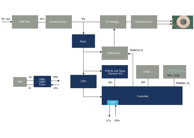
The coil parameters can be calibrated during assembly on the production line. The benefit of the solution is that coil calibration data is written to the WP300TX IC during product test. This results in consistent operation across product and reliable performance. Finally, to create 1:1 pairing between the transmitter and receiver, secure communications can be included in-band to make sure only receiver devices that are authenticated by the transmitter are powered. Figure 4 includes block diagrams of a 300W transmitter controller and 300W receiver controller that have been optimized to deliver these capabilities.
300W Transmitter
300W Receiver
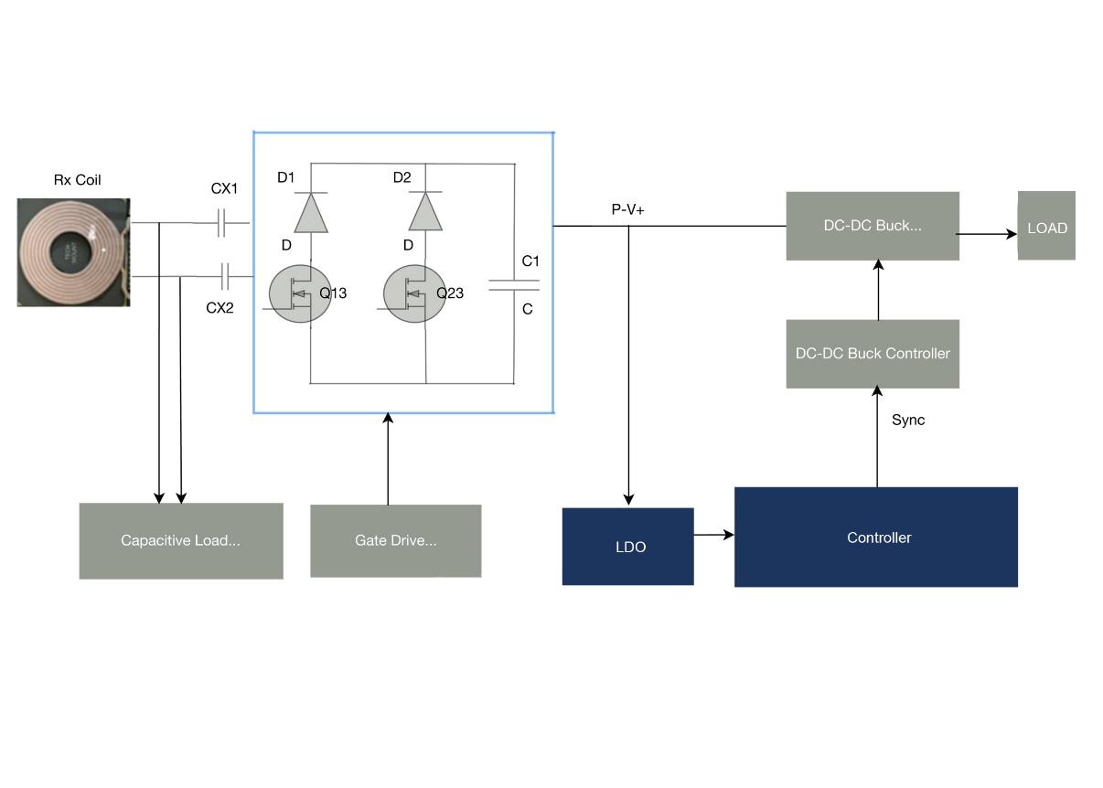
Block diagrams of transmitter and receiver circuitry that have been optimized for wireless charging.
System developers should work with a supplier that provides detailed guidelines for using their wireless charging solutions including component selection, coil design and board layout. Suppliers should also provide step-by-step guidance to ensure seamless execution of the final product. With this approach, developers can save time, mitigate risk, and simplify their wireless charger designs so that they deliver on the full promise of electromagnetic induction technology, while also improving their productivity, reducing manufacturing cost and improving safety and security.
The content & opinions in this article are the author’s and do not necessarily represent the views of RoboticsTomorrow
Featured Product