Motion control systems with brushless DC, voice coil or three-phase direct drive actuators use a position servo controller that dynamically changes the current in each motor phase.
Enabling Peak Servo Performance with Thermal Protection
Yegor Rabets, Electronics Team | Zaber
Motion control systems with brushless DC, voice coil or three-phase direct drive actuators use a position servo controller that dynamically changes the current in each motor phase. These actuators are almost always driven with the minimum current required to maintain their trajectory. We can take advantage of this phenomenon by occasionally requesting brief bursts of relatively high current which can improve the system's overall performance—for instance, to keep up with a more aggressive trajectory or to overcome stronger disturbances. Luckily, in many applications only brief bursts are required to significantly boost performance. As an example, the figure below shows the typical motor phase currents in Zaber's X-LDA stage during a move with very high acceleration.
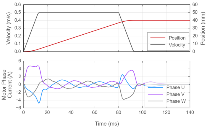
Figure 1: Typical phase currents in Zaber's X-LDA stage during a very aggressive trajectory, with just over 4g (40 m/s²) of acceleration. Note that the X-LDA's continuous current limit of 2.5 A is exceeded during acceleration and deceleration, but not when moving at constant velocity.
In order to maintain safe motor temperatures during these bursts of relatively high current, actuators that use a servo controller have a specified continuous (RMS) current limit that can be sustained indefinitely and an instantaneous ("overdrive") current limit that may only be used for brief durations. How do we know when it is safe to use overdrive currents above the continuous limit? Simply put, we need to intentionally balance these bursts with sufficient periods of cooling in between. The most common strategy for doing this is to monitor the motor temperature, either by measuring it directly or by estimating it computationally.
Common thermal protection methods
Motor temperature sensors
Temperature sensors that are integrated into the motor windings provide a direct reading of the motor temperature. In situations where heat builds up slowly in the motor windings and can be assumed to be uniformly distributed in the motor, integrated sensors provide the most accurate data. However, the time constant of thermal conduction across all phases in a motor winding is often longer than the brief bursts of overdrive currents. Hence, an embedded temperature sensor may not respond quickly enough to protect against localized hot spots created by high current loads in imperfectly uniform motor winding wires.
Thermal models
Thermal models attempt to estimate the thermal state of a system based on observable non-temperature variables. In most actuators, the primary sources of heat generation are resistive losses in the motor windings and Eddy currents resulting from alternating current in the windings. Both of these are related to motor current, so the temperature of a motor is usually estimated using the history of current driven into the motor and the motor's thermal properties. Thermal model methods that require knowing the motor's thermal properties are very common, but their main disadvantage is that thermal data is not readily available for most motors.
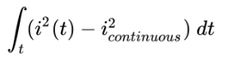
I²t
The industry standard I²t algorithm is a specific type of thermal model that is simplified to not require any explicit thermal parameters. In its most basic formulation, I²t simply defines an excess thermal energy pool that an actuator is allowed to use in addition to the thermal energy generated by the actuator's continuous current. The name I²t is derived from the fact that the heat generated in a motor is proportional to the current squared. The algorithm simply monitors the square of current over time, and integrates the difference between instantaneous currents and the continuous current limit:
 |
(1) |
In addition to motor current limits, the only parameter required for an I²t algorithm is the maximum allowed I²t integral, which essentially defines an amount of excess thermal energy allowed in the motor. When the I²t integral surpasses this pre-defined threshold, motor current is typically throttled back to the continuously permitted limit to prevent further heating.
Thermal protection in Zaber products
All of Zaber's linear motor and voice coil products use the I²t algorithm for ensuring overdrive currents are used safely. As an additional level of protection, linear motor products also have a thermal switch integrated into the motor. The integrated thermal sensor helps protect against slow temperature rises in situations with sub-optimal heat sinking or from elevated ambient temperatures. The I²t algorithm mainly helps protect against relatively fast surges of heat generated by bursts of peak power.
Overdrive limits in Zaber's ASCII Protocol
When powering linear motor and voice coil positioners, Zaber's motor drivers maintain concurrent and completely independent I²t models for both the driver and the motor. The axis driver and motor have different current limits and I²t integral ("excess energy") thresholds.
The motor's current limits are described by the following three settings:
- motor.current.continuous.max: the motor's continuous current limit
- motor.current.overdrive.max: the motor's overdrive (instantaneous peak) current limit
- motor.current.overdrive.duration: the duration for which the motor can withstand its maximum overdrive current
These settings also define the motor's I²t integral limit. In units of Amperes squared seconds (A²s), this limit is:
|
Motor's I²t limit = 0.0004 × (motor.current.overdrive.max ² - motor.current.continuous.max ²) |
(2) |
An analogous group of three settings describes the driver's current limits and I²t integral limit (in units of A²s):
- driver.current.continuous.max: the driver's continuous current limit
- driver.current.overdrive.max: the driver's overdrive (instantaneous peak) current limit
- driver.current.overdrive.duration: the duration for which the driver can output its maximum overdrive current
|
Driver's I²t limit = 0.0004 × (driver.current.overdrive.max ² - driver.current.continuous.max ²) |
(3) |
One way to think about these limits is "if a constant current needs to be applied, how long can that current be sustained?". Alternatively, "if I have to apply a constant force for a given period of time, how large of a current can I drive?". The answers to both of these questions can be inferred from an I²t curve such as the one below. Notice that depending on the driver and motor properties, in some regimes the driver settings may be more limiting while in others the motor settings may be more limiting. Unfortunately, motor currents in a real world scenario are far too complicated and dynamic for the I²t plots to provide any detailed insights, but this graphic is nonetheless useful for building up some basic intuition.
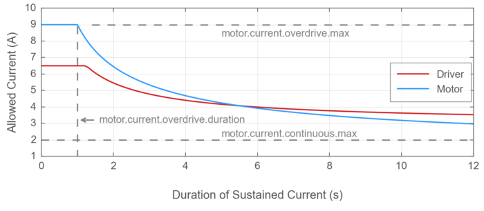
Figure 2: An example I²t curve showing how the duration of sustained current changes depending on the current magnitude.
The six settings described so far define the driver's and motor's absolute limits, and are not modifiable. The actual continuous and overdrive currents that an axis servo controller may use are adjustable using the following two settings, as long as they adhere to the absolute limits:
- driver.current.continuous: the maximum current that a servo controller may output continuously
- driver.current.overdrive: the maximum current that a servo controller may output for brief durations
Note that if driver.current.continuous is adjusted below both the driver's and the motor's absolute limits, then the new value will override the lower of the driver's or motor's continuous current limits in Equations 2 or 3. This ensures that changing the continuous current limit does not affect the durations that overdrive currents may be delivered for.
The percentage of I²t that a driver or motor model has consumed relative to its limit can be queried with two diagnostic settings:
Overdrive Recovery
Most of the time, the axis driver of a linear motor or voice coil positioner will deliver currents up to driver.current.overdrive as required for reaching the trajectory position, force, or torque target set points. The axis driver maintains independent I²t calculations to monitor the excess thermal ("overdrive") energy in each phase of the driver and each phase of the motor while each motor phase's currents rise above or fall below the respective model's continuous limit. If the measured excess thermal energy in an I²t model for any driver phase or any motor phase exceeds the overdrive energy limit, the axis driver initiates an overdrive recovery response.
In some implementations of I²t, it is common to throttle back motor current to the continuous limit (in Zaber's case, this would be driver.current.continuous) as soon as the I²t integral limit is exceeded. The main downside to this approach is that with reduced thrust or torque in the motor, the axis may deviate from its planned trajectory and may reach an undesirable or dangerous position. Other implementations of I²t disable the driver altogether and allow the motor to coast to a stop, relinquishing control of the actuator. Zaber controllers, however, will first attempt to bring the motor to a controlled stop using the full driver.current.overdrive if it is required. The controlled stop attempt is aborted if it causes the I²t integral to further increase above a slightly higher secondary I²t limit. After the controlled stop attempt, the axis driver is finally allowed to throttle back servo current for the faulted axis.
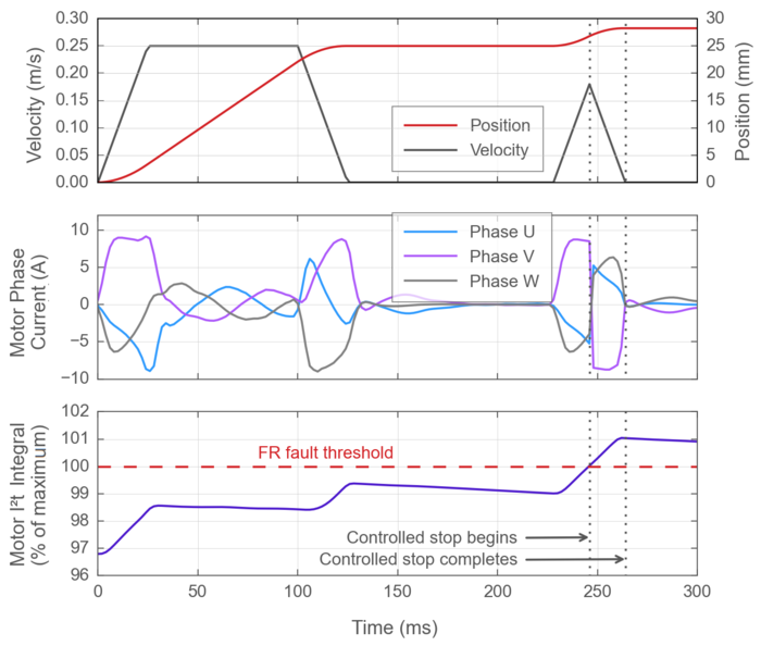
Figure 3: A detailed look into the overdrive fault response on Zaber stages. Notice that the measured motor I²t integral (motor.i2t.measured) ramps up during periods of higher currents and slowly ramps down during periods of lower currents. Currents are not throttled back immediately upon exceeding the overdrive limit, but only after the axis comes to a controlled stop.
Upon detecting an overdrive limit fault, the controller raises an Overdrive Limit Exceeded (FR) warning flag that will persist until cleared with a warnings clear command. Additionally, motion commands will be rejected with the reason OVERDRIVELIMIT until both the driver's and the motor's I²t models have cooled down and driver.i2t.measured and motor.i2t.measured both fall below 100 for 1 second.
During the cool-down period after the fault-triggered stop, the axis will try to hold its position using phase currents reduced to driver.current.continuous.
Common Setting Modifications
Disabling Overdrive
Overdrive is enabled by default on most of Zaber's linear motor and voice coil devices. In some applications, brief bursts of higher available power may not provide any useful benefits, and it may be desirable to be able to maintain a consistent current limit indefinitely. The easiest way to do this is to set driver.current.overdrive on that axis to 0. The following example disables the use of overdrive currents on device 2's axis 1:
/2 1 set driver.current.overdrive 0↵
@02 1 OK IDLE -- 0
Reducing the Overdrive Current to Match the Capabilities of a Power Supply
In some applications, space or cost constraints or other considerations may require a Zaber actuator to be powered with a smaller power supply than is typically recommended for the device. In these situations, the attempted bursts of overdrive, although brief, may exceed the capabilities of the power supply, causing the power supply to engage its overcurrent protection mechanism and either completely disable its output or lower its output voltage. This will manifest in an Overvoltage or Undervoltage Driver Disabled (FV) or a Current Inrush Error (FC) warning flag, or complete power loss to the controller.
To avoid this, it should be possible to reduce the overdrive current limit to match the power supply's capabilities. Please note that the supply current does not have a one-to-one mapping to the motor's phase current. On single phase motors (eg. voice coils) or three phase motors (eg. three-phase direct drive or brushless DC motors), the supply current is almost always smaller than the current delivered to a motor phase. For more details, please see driver.current.overdrive.
Decreasing the Average Heat Generated by an Actuator
Although driver.current.continuous may be exceeded for brief durations, the I²t algorithm that controls the delivery of overdrive currents ensures that over long time periods the root mean square (RMS) current for any motor phase on an axis remains below driver.current.continuous. As a consequence, the driver.current.continuous setting essentially controls the steady-state heat dissipation of an axis. To limit the average heat generation of an actuator, we can keep driver.current.overdrive the same and simply reduce driver.current.continuous. The actuator's peak thrust or torque will remain the same, but the continuous thrust or torque will decrease proportionally.
Changing the Duration of Allowed Overdrive Current
This is presently not possible with Zaber's ASCII protocol. A device's current limits can be decreased, but once defined by product configuration the overdrive energy limit of an actuator will remain the same relative to its original continuous limits. To change a device's allowed overdrive duration (and therefore the energy limit), please contact Zaber Technical Support.
The content & opinions in this article are the author’s and do not necessarily represent the views of RoboticsTomorrow
Comments (0)
This post does not have any comments. Be the first to leave a comment below.
Featured Product