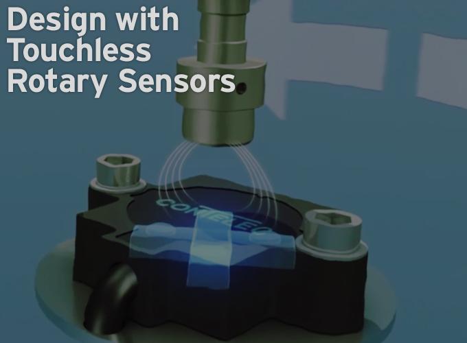
Touchless rotary sensors are position sensors that use a position marker attached to an applications rotating part plus a sensor to measure the markers angle.
Contributed By | Novotechnik U.S., Inc.
This white paper describes how rotary motion applications can benefit from new technology, that provides engineers with more design flexibility. It also describes how some touchless devices can be user customized.
Touchless rotary sensors are position sensors that use a position marker attached to an application’s rotating part plus a sensor to measure the marker’s angle.
Other noncontact magnetism-based sensors go beyond potentiometric sensors using resistance-based track-and-wiper techniques. However, they still require that a shaft be attached to the sensor’s housing.
In contrast, touchless rotary sensors use a magnetism-based measurement technique that doesn’t require physical contact between the marker and sensor. As we’ll explore, this setup provides several benefits to a wide range of applications.
How touchless rotary sensors work
In touchless rotary sensors, a permanent magnet attached to a rotating shaft is used as a position marker. As the shaft rotates, a separate sensor unit tracks the orientation of a magnet using the Hall Effect — the voltage difference across an electrical conductor in which an electric current flows in the presence of a magnetic field. The direction of the potential difference is perpendicular to both the magnetic field and current. The magnetic field’s measured orientation is captured by an integrated circuit. The shaft’s calculated angle is then transmitted, most commonly as an analog output.
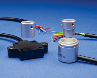
Touchless rotary sensors allow programmable angle ranges and have body diameters of 13 to 90 mm.
Note that while the term touchless rotary sensors is common in the U.S., the terms noncontact rotary sensors or noncontact rotary encoders are used in Europe. The U.S. use of touchless rotary sensors differentiates these components from potentiometric as well as other noncontact technologies.
Touchless sensor uses
Touchless sensors often offer distinct advantages over potentiometric track-and-wiper components and noncontact sensors. They’re the more suitable technology when:
- An application requires measurements through a nonmagnetic wall or plate
- The application is in an extreme environment, necessitating a sensor shaft to seal, or
- The drive shaft has a lot of play or vibrates. In fact, touchless rotary sensors are the only option in a few application types:

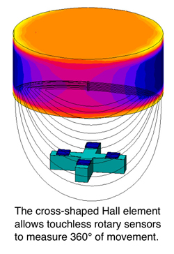
These sensors employ a cross shape directly affixed to a silicon chip, so the sensor produces both sinusoidal and cosinusoidal output signals and measures X and Y-oriented magnetic fields.
Applications through thin walls: Consider a hydraulic swashplate pump with a set internal pressure. Here, the field of a magnet mounted on a drive shaft inside the pump protrudes through its nonmagnetic wall plate. From outside the pump, a touchless rotary sensor tracks the orientation of the magnetic field for angle-measurement purposes.
Applications with very low friction-torque requirements: Shaft seals typically introduce a lot of friction torque. This adds to a design’s hysteresis errors, particularly when the torque provided by the drive shaft is low — as in dancer-arm and wind-vane applications. Touchless rotary sensor’s magnetic markers attach directly to an application’s rotating shaft so they introduce zero friction-torque avoiding that issue entirely.
Applications in which misalignment is problematic: Touchless rotary sensors overcome driveshaft misalignments more easily than other sensors, as there is no flexible precision coupling needed.
Touchless-sensor advantages
Touchless rotary sensors offer four main benefits: Low operating cost, ruggedness, reliability, programmability, and simplicity.
Cost: Touchless rotary sensors can have a bit higher initial cost than alternatives, but not always: Their initial cost can be lower than other sensor options when the latter necessitates expensive subcomponents such as ball bearings or expensive precision shaft couplings.
Ruggedness: The working core of a touchless rotary sensor is never exposed to the environment. The magnet is exposed, so it is often potted with ingress-resistant compounds, particularly when it will be exposed to fluids. Touchless rotary sensors exhibit no mechanical wear on the sensor parts. Therefore, their sensor life is defined not in cycles, but usually as Mean Time To Failure MTTF. This calculated value largely depends on the quantity and type of electronic parts used in the sensor core and can be as long as hundreds of years.
Programmability: For programmability, touchless sensors can leverage the fact that there’s a printed circuit board (PCB) with electronics within the sensor core. PCBs are easily set up for expanded functionality, and allow quick calibrations of start and end angles. They also allow one-point calibration — for setting the center position for a joystick or the steering angle feedback on mobile applications, for example.
Some engineers using touchless sensors buy the programmable subtype in bulk, even if all the installation points don’t necessitate programmability. That way, they don’t need to know upfront the required angle to be sensed at each installation point, and they can use one sensor model on multiple installation points necessitating that different angles be measured.
Simplicity: Engineers working on larger projects can forgo the customer-programmability functionality and get preprogrammed touchless rotary sensors. Precalibrated sensors are also useful when (for safety reasons) it’s better that the sensors’ functionality be unalterable. Nonprogrammable sensors require no secondary microprocessor for calibration and look-up table purposes, so they are also less expensive.
In some cases, engineers buy programmable touchless sensors to “play around” and try different prototype setups. Then they switch to lower-cost fixed-angle sensors when the finalized design is sent to production.
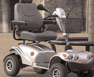
One touchless rotary sensor application is on a motorized wheelchair’s joystick. It uses three Vert-X rotary sensors allowing the rider to control acceleration, steering and braking.
Magnet and sensor sizing and installation
Both the sensor and the position marker attached to machine’s rotating component being tracked must be properly sized and positioned for reliable operation. Several subtypes exist to accommodate different application geometries and requirements.
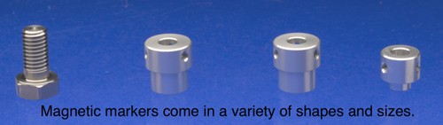
Mounting and sizing the magnet marker: The magnet markers for touchless rotary sensing come in several different body styles. These markers either screw into the rotating component (so that the axes of rotation are aligned) or they clamp onto the rotating member’s shaft.
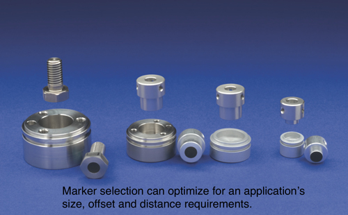
The working distance between magnet and sensor as well as the permissible installation tolerance in the Z axis dictates the best magnet size. Conversely, an engineer can pick a larger magnet to compensate for axial offset in the X-Y direction and maintain constant linearity and avoid a drop in the axial tolerance band.
Specifications: Standard touchless sensors measure rotary movements from 0° to 360° with repeatability from 0.1° to 0.12°. Resolution is 10 to 12 or 14 bit. Linearity — the maximum deviation of the electric output signal from the ideal proportional straight-line relationship of the mechanical input angle to the electrical output signal — can be 0.3% to ±0.5% or ±1% depending on the sensor. Most of the sensor units are rated to IP69K and the markers attached to the rotating system components can withstand even harsher application conditions.
Mounting and sizing the sensor: For mounting the sensor unit, touchless rotary sensor systems come with traditional servo-type mounts or two to four-screw mounts. The most suitable choice depends on how the sensor is best attached — to the front or back of the rotating machinery, for example. Several sensor bodies feature mounting holes and slots and screws. These allow the sensor to be rotated to an optimal mounting position before being secured. Here, pre-tightened screws allow the installer to align the sensor to the mechanical zero or center position of the marker-fitted driveshaft. Then the secured sensor outputs the desired voltage at key angles. For even more mounting flexibility, some sensors can also be mounted with a clamp that allows full rotation. The most suitable sensor size depends on three factors:
- The space available on the machinery
- The electronic functionality needed — because more complex applications necessitate larger sensors to accommodate more electronics inside
- The level of robustness needed. For example, applications in extreme environments may require a sensor with a thicker stainless-steel housing and a solid cable with strain relief.
Note that in some cases, application design features and manufacturing tolerances cause axial offsets between the rotating component being tracked and the sensor axis. Such radial misalignment degrades measurement results because axis twist generates erroneous angle data. In such instances, reliably linking the sensor to the marker’s magnetic output requires an installation that meets published guidelines.
Environmental considerations: Sensors that necessitate rotary shaft seals can be problematic in washdown and other harsh applications. In contrast, touchless rotary sensors incorporate potted electronics or O-ring sealed housings to minimize such issues. The sensors’ potted electronics and stainless-steel housings withstand vibration and shock. Likewise, the magnets are usually potted and well secured against shock and vibration.
The temperature rating of touchless rotary sensors satisfies about 95% of all industrial and mobile applications. Standard sensor systems operate in temperatures from -40°C to +85°C or even to +105°C for some sensor units. (The limiting factor is the sensor core’s electronics.) Electronic compensation to correct for temperature isn’t required, as touchless rotary sensor output is unaffected by temperature extremes within the above operating ranges.
Outputs: Unlike most Hall sensors that use a semiconductor to measure the strength of a magnetic field perpendicular to the element itself, touchless rotary sensors measure 360° and produce sinusoidal and cosinusoidal output signals. By normalizing these signals, a touchless rotary sensor’s microprocessor determines the marker’s orientation.
Once the orientation is determined, most touchless-sensor applications need analog outputs, mostly 0.1 to 5 V, 0.1 to 10 V or 4 to 20 mA. Elsewhere, incremental outputs are used for speed-control applications. Digital outputs (such as CAN Open) are used for mobile applications — marine- vessel controls and garbage-truck trashcan handling, for example. SSI output is used with PLCs for maximum resolution and omission of multiple D/A and A/D conversions.
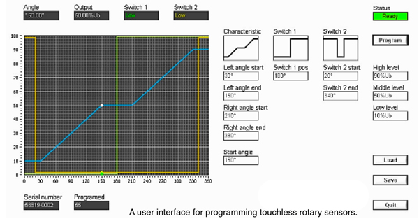
Programming the installation: The newest touchless rotary sensors can be connected to USB adapters. These transmit data between the sensor and a user interface on a standard PC for programming. User-friendly software allows readouts and graphic displays of sensor output and adjustments for multiple parameters: Start angle, end angle, different types of output curves including positive and negative slopes, and changes in steepness for greater resolution around critical angles — as on throttle valves, for example. USB connections can also be set up to output custom nonlinear curves.
Touchless rotary sensors are sometimes set up to trigger switches. Here, transistor- transistor logic (TTL) switch outputs are also programmable. These can turn relays on or off; prompt angle-range-dependent light or sound warnings; or initiate a screen to display shaft position. Some outputs can even trigger displays without using a voltmeter. For example, a low-current display LED attached directly to a switch output can indicate center position. The output is simply programmed to light the LED when that position is reached.
How to connect touchless rotary sensors: The connections to and from a touchless rotary sensor unit depend on the application’s required level of programmability, output type, and the presence of switches when applicable.
Supply voltages range from 5 to 30 V — with 12 and 24 V supply voltages most common for units with five leads. The number of leads to connect depends on the output and switch options. Up to 10 leads are needed for advanced sensor configurations.
For applications using simple non-programmable touchless sensors, three wires for analog outputs — Supply, Ground, and Signal Out — are all that is needed. Signal conditioners are usually not needed, as all sensors have active outputs.
Digital outputs require more wires — to accommodate the programming of start and end angles, center position, range, the Supply, Ground, and Signal Out. Finally, some sensors have current outputs to cover long cable distances with low losses and minimal noise problems. For more information, consult the literature for the specific unit you’re installing.
Touchless-sensor design tradeoffs
As with any component, touchless rotary sensors sometimes necessitate design tradeoffs. The first is cost: Touchless rotary sensors can be more costly if they must span larger distances, because such installations require bigger magnets. Remember that larger magnets are more expensive and require more space, but they allow the sensor to be installed farther away from the marker or even on the outside of a piece of machinery or control space, for example. Larger magnets also allow sensor units to be offset from the marker-fitted shaft if the machine geometry requires it.

A 90 mm diameter sensor with top and bottom views of marker.
The second tradeoff is the risk of degraded performance in the presence of metal shavings. In some applications, magnetic particles can gather on the magnetic marker. Such debris can cause hysteresis and offset errors, so measures must be taken to prevent that from happening.
To sum up, touchless rotary sensors can provide advantages over other technologies and even solutions to angle measurement that would be difficult or impossible to achieve otherwise. Some touchless sensors can be programmed at the factory or by users for customization. Applying touchless sensors have a few more considerations than track and wiper sensors, though with manufacturers manuals, they are pretty straight forward to incorporate in most applications.
 About Novotechnik U.S., Inc.
Novotechnik develops and produces a wide variety of rotary sensors and linear transducers of contacting and non-contacting technologies.
These are used in a wide range of motion control applications in automotive, renewable energy, machine engineering, plastics, hydraulic, pneumatic, and medical equipment industries.
Novotechnik introduced the potentiometer to the machine controls industry in the 1950s. . Since then, the company has developed rotary and linear position sensing technologies that set the standard with outstanding linearity and reliability over an extended operating life.
Today, Novotechnik has developed new technologies that raise the standards, bringing a new level of linearity and reliability to non-contacting applications. These technologies include NOVOSTRICTIVE® magnetostrictive technology, INDRES® inductive-resistive technology, and Vert-X® Hall technology.
The content & opinions in this article are the author’s and do not necessarily represent the views of RoboticsTomorrow
Featured Product