This whitepaper will delve into the steps and techniques necessary for mitigating electrical noise in servo systems, ensuring optimal performance and reliability for high-precision applications.
 Optimizing Servo System Performance: A Comprehensive Guide to Eliminating Electrical Noise and Enhancing Noise Immunity
Warren Osak | Servo2Go
Electrical noise, or electromagnetic interference (EMI), is a significant concern for engineers and designers working with servo systems. EMI can manifest in various forms, such as radiated or conducted noise, and can lead to performance degradation, signal interference, and reduced system accuracy. In servo systems, noise can corrupt critical signals such as position and velocity feedback, affecting overall stability and control. As an engineer with expertise in the field, it is crucial to understand the sources of noise in servo systems and employ effective strategies to minimize or eliminate its impact.
This whitepaper will delve into the steps and techniques necessary for mitigating electrical noise in servo systems, ensuring optimal performance and reliability for high-precision applications.
Let’s go through the steps together:
1. Proper grounding: Ensure that your servo system is grounded properly. Use a single-point grounding technique to minimize ground loops and connect all the grounds to a common point.
a. Single-point grounding: Connect all grounds to a single, common point to reduce ground loops and potential differences.
b. Star grounding: Attach individual ground wires from components to a central ground point, lowering noise levels.
c. Grounding best practices: Utilize thick, low-impedance wires, keep wire lengths short, and maintain clean, secure connections.
2. Shielding: Use shielded cables for power and signal connections to reduce electromagnetic interference. Connect the shield only at one end, typically the controller end, to avoid ground loops.
a. Cable shielding types: Select the appropriate shielding type, such as foil or braided shielding, based on the specific application and interference levels.
b. Proper grounding of shield: Ground the shield at one end, typically the controller end, to avoid ground loops and maximize noise reduction.
c. Shield continuity: Ensure continuous shielding coverage throughout the cable length, including cable joints, connectors, and junction boxes, for optimal noise suppression.
3. Cable routing: Separate power and signal cables to minimize crosstalk. If they must cross, do so at a 90-degree angle. Avoid running cables parallel to each other or in close proximity.
a. Physical separation: Maintain a minimum distance between power and signal cables, routing them in separate conduits or cable trays when possible.
b. Crossing at right angles: If power and signal cables must cross, do so at a 90-degree angle to minimize the coupling of interference between the cables.
c. Avoid parallel runs: Refrain from running power and signal cables in parallel or close proximity for extended distances, as this can exacerbate crosstalk and noise coupling.
4. Cable selection: Use cables with twisted pairs, as they can significantly reduce noise by cancelling out electromagnetic interference.
a. Twisting effect: Twisted pair cables reduce noise by equalizing the exposure of each conductor to external interference, causing the noise to cancel out when the differential signals are combined.
b. Choose appropriate cable types: Select cable types, such as shielded twisted pair (STP) or unshielded twisted pair (UTP), based on the application's susceptibility to interference and the required level of noise immunity.
c. Match impedance: Ensure that the cable impedance matches the impedance of the connected devices to minimize signal reflections and maintain signal integrity.
5. Noise filtering: Employ noise filtering techniques, such as ferrite beads or chokes, to suppress high-frequency noise in power and signal lines.
a. Ferrite beads: Install ferrite beads on cables to absorb high-frequency noise and convert it into heat, effectively reducing EMI.
b. Chokes and inductors: Use common-mode chokes or inductors to suppress noise by increasing the impedance for common-mode currents while allowing differential-mode currents to pass through with minimal attenuation.
c. Filter circuits: Implement passive or active filter circuits, such as low-pass filters, to attenuate high-frequency noise while allowing desired signals to pass through.
6. Using the proper power supply: Use a regulated power supply with low noise output for your servo system. Ensure that it has sufficient capacity to handle the load and can maintain a stable output voltage.
a. Power supply capacity: Ensure the power supply has sufficient capacity to handle the load and maintain a stable output voltage under all operating conditions.
b. Low-noise output: Choose power supplies with low output noise and ripple specifications to minimize the introduction of noise into the servo system.
c. Power supply filtering: Employ additional filtering, such as capacitor banks or inductors, on the power supply output to further reduce noise and maintain clean voltage rails for the servo system.
7. Minimize inductive loads: Keep inductive loads, such as motors, transformers, and solenoids, away from your servo system and its cabling.
a. Physical separation: Maintain a safe distance between inductive loads and servo system components or cables to reduce the coupling of electromagnetic fields.
b. Shielding inductive loads: Use shielding materials or enclosures around high-current inductive components to contain their magnetic fields and reduce the impact on nearby servo systems.
c. Minimize switching transients: Implement snubbers, flyback diodes, or other transient suppression techniques to reduce voltage and current spikes generated by inductive load switching.
8. Use differential signalling: Utilize differential signalling for critical signals, such as encoder feedback, as it offers better noise immunity compared to single-ended signalling.
a. Differential transmission: Transmit signals as a pair of complementary voltages, where the receiver detects the difference between the two voltages, rejecting any common-mode noise picked up along the transmission path.
b. Balanced impedance: Ensure that the impedance of the two conductors in a differential pair is closely matched, which helps to maintain signal integrity and reduce noise susceptibility.
c. Differential receiver: Use differential receivers designed to amplify the voltage difference between the two input signals while rejecting common-mode noise and interference.
9. Check for ground loops: Inspect your system for ground loops, which can be a source of noise. Use isolation techniques, such as optoisolators, to break ground loops if necessary.
a. Identify ground loops: Use a multimeter or oscilloscope to measure potential differences between various ground points in the system, which may indicate the presence of ground loops.
b. Isolation techniques: Use optoisolators, isolation transformers, or other isolation devices to break ground loops and prevent noise from circulating through the system.
c. Proper cable grounding: Ensure that signal and shield grounding is done correctly, with single-point grounding techniques employed to minimize the chance of ground loops forming.
10. Proper component selection: Choose components, such as servo drives and controllers, with built-in noise filtering and immunity features. If not available, install external EMI-RFI Filters to sensitive equipment.
a. Noise immunity specifications: Select components with robust noise immunity specifications, such as high common-mode rejection ratio (CMRR) and good electromagnetic compatibility (EMC) performance.
b. Integrated filtering: Opt for components with built-in filtering capabilities, such as EMI filters or low-pass filters, to reduce the impact of noise on the system's performance.
c. Compliance with standards: Ensure that the selected components comply with relevant industry standards for noise and interference, such as FCC, CE, or IEC standards, which can provide a baseline for acceptable noise performance.
11. Regular maintenance: Regularly inspect and maintain your servo system. Check for loose connections, damaged cables, and worn-out components that can contribute to noise.
a. Inspect cables and connections: Periodically check cables for damage, fraying, or loose connections that could contribute to noise or signal degradation. Replace any damaged cables as needed.
b. Verify grounding integrity: Ensure that grounding connections remain clean, secure, and free from oxidation, which can increase contact resistance and reduce noise suppression effectiveness.
c. Monitor component health: Routinely assess the condition of critical components, such as motors, encoders, and controllers, and replace any worn-out or faulty parts to maintain optimal system performance and noise immunity.
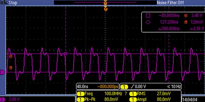
12. Test and analyze: Use an oscilloscope or spectrum analyzer to identify the source of the noise and verify the effectiveness of your noise-reduction efforts. Make adjustments as needed to further reduce electrical noise.
a. Noise source identification: Analyze the system's noise profile and frequency spectrum to pinpoint the sources of interference and target your noise-reduction efforts more effectively.
b. Evaluate noise mitigation techniques: Test the effectiveness of implemented noise reduction measures, such as shielding, grounding, or filtering, by comparing the system's noise performance before and after the changes.
c. Iterative improvements: Continuously refine and optimize your noise reduction strategies based on test results and analysis, ensuring the highest possible level of noise immunity and system performance.
Other Considerations/Factors:
While the steps and techniques mentioned above cover most of the critical aspects of eliminating electrical noise in servo systems, there are a few additional considerations and outliers to factor in:
1. Environmental factors: Be aware of external noise sources, such as radio frequency interference (RFI) from nearby equipment, wireless devices, or high-power electrical systems, which may require additional shielding or isolation measures.
2. System-level design: Consider the overall architecture and layout of your servo system, including component placement, cable routing, and enclosure design, to minimize noise coupling between different parts of the system.
3. Software-based filtering: Implement software-based filtering techniques, such as digital filtering or signal processing algorithms, to further improve the noise immunity of your system by eliminating noise from the acquired data or control signals.
4. Training and education: Ensure that the engineering and technical staff working on the servo system are well-trained and knowledgeable about noise reduction techniques, as well as best practices for system installation, setup, and maintenance.
5. Customized solutions: Recognize that some applications or environments may require customized noise reduction solutions, which could involve specialized components, materials, or techniques tailored to the specific challenges of the application.
6. Keep up-to-date with advancements: Stay informed about new technologies, materials, or methods that may emerge for reducing electrical noise in servo systems. Incorporating the latest advances can help improve the performance and reliability of your system.
By following these guidelines, including proper grounding, shielding, cable routing, noise filtering, component selection, and regular maintenance, engineers can effectively minimize the impact of EMI on servo system performance and maintain the highest level of accuracy and stability.
About Electromate Inc.
Electromate Inc., under the leadership of its founder and President, Warren Osak, is a renowned and respected industrial automation distributor specializing in providing advanced motion control, and robotic and mechatronic solutions. With > 35 years of experience and deep technical expertise in the field of automation, Electromate is committed to offering guidance and sharing knowledge to help engineers overcome challenges and optimize their servo systems for a variety of demanding applications.
The content & opinions in this article are the author’s and do not necessarily represent the views of RoboticsTomorrow

Servo2Go.com Ltd.
Servo2Go.com is an Online E-Store Distributor of Automation & Motion Control Systems & Components including: Servo Motors & Drives, Stepper Motors & Drives, Automation & Motion Controllers, HMIs, Positioning Systems & Actuators, Gearboxes, Couplings, Brakes, Encoders, Tachometers and Linear Displacement Transducers. Servo2Go.com is an ISO9001:2015 Registered Company.
![]()
![]()
![]()
![]()
Other Articles
The Emergence of Mechatronic Subsystems and Their Importance in Product Deployment
The Importance of the Speed-Torque Gradient in DC Motor Sizing
Understanding the Motor Constant in DC Motor Sizing
More about Servo2Go.com Ltd.
Featured Product