This paper reviews the concept of Functional Safety as it relates to machinery. The design steps for a safe machine are outlined and the methodology for determining appropriate PL/SIL safety ratings discussed.
Machine Functional Safety – PL and SIL Ratings
Article from | Genesis Motion Solutions
The most common motion control Safety Functions are presented. The paper concludes with a review of the system architectural implications of machine safety.
Machine Safety
There are formal steps to guide the design of a safe machine. The process is rigorous and well documented in a range of standards including the Machinery Directive (2006/42/EC). Greater insight into the process can be gained, however, by working through an example.
Step 1. Specification and Modes of Operation
First, define the performance characteristics (speed, payload etc.) and modes of operation (setup, runtime, maintenance etc.) for the cobot.
- Robot must move at 3 m/sec to achieve productivity goals.
- Robot must also perform some tasks with a human present in the work zone (multiple times per day.)
- When the operator is in the robot workspace, speed must be reduced by 90%.
- Operator must be able to teach a path though space by moving the robot by hand with power applied.
- Maximum payload is 5 Kg.
Step 2. Hazard Identification
Next, the systematic identification of hazards during all phases of the machine life cycle. Typical machine hazards to humans include crushing and/or severing of fingers, puncture wounds, entrapment and entanglement, burns, high audible noise.
The primary hazards for the cobot example are crushing of fingers and puncture wounds.
Step 3. Risk Assessment
Risk assessment uses a range of scoring tools based on the severity of a hazard and the probability of it occurring. The tools vary by industry and region but employ the same basic techniques. The end result is a quantification of Original Risk.
Step 4. Risk Reduction
Reduction of Original Risk to Acceptable Residual Risk follows a three-level method. The definition of Acceptable Residual Risk varies by industry and region. Machine builders may also decide to reduce Acceptable Residual Risk beyond the regulated level.
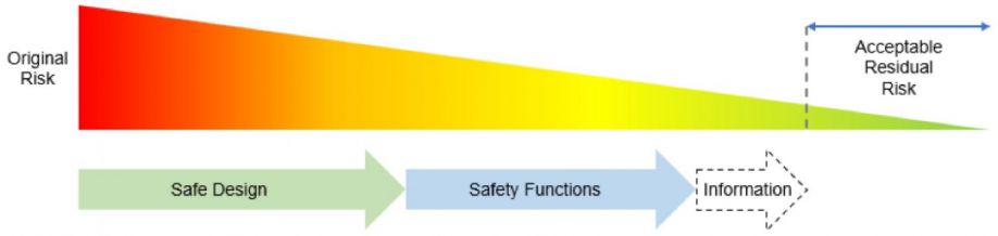
Fig. 1
L1: Safe Design Safe
Design employs inherent protective measures which may have a negative impact on machine performance. Some interpretations of the process include the use of physical guarding as part of the Safe Design.
In the cobot example, Safe Design techniques include limiting the speed (low bus voltage with appropriate motor back-EMF constant), using motors capable of very limited torque, and smooth rounded surfaces.
In this machine, the robot surfaces and end-effector, by design, will not cause puncture wounds. Risk has been reduced, but not to an acceptable level. The robot is capable of high speeds when a human is present and the maximum payload requires sufficient torque to cause injury. The risk of crushed fingers must be addressed as well as the need for safe teaching.
L2: Safety Functions
There are a range of standard, pre-defined Safety Functions. They are reviewed in detail in the Safety Functions section. For this design, Safe Limited Speed (SLS) and Safe Torque Off (STO) are appropriate. SLS will ensure that the robot speed stays below a safe limit in the presence of an operator. STO will ensure that the motors can generate no torque during path teaching.
L3: Information
If the Safety Functions used do not reduce the risk to an acceptable level, information, in the form of warnings and/or direction to wear protective equipment must be posted on the machine.
Safety Function Rating – PL and SIL
Once the Safety Functions are defined it is necessary to determine their required ratings. PL (ISO 13849-1) and SIL (IEC 62061) are two different paths to the same destination – a safety rating for a Safety Function. PL is machine-centric whereas SIL has its origins in the process industries. IEC 62061 is a newer SIL standard focused on machine safety but for electrical control systems only – pneumatics and hydraulics are not included. In general, a Safety Function has both a PL and SIL rating.
A machine may have a range of Safety Functions with different SIL/PL ratings. It is a common misconception that a complete machine or components in the machine have PL/SIL ratings. An encoder, for example, is specified as suitable for use in a PL/SIL rated Safety Function but is not individually PL/SIL rated.
To determine the required PL/SIL rating for a Safety Function, a risk analysis must be performed based on severity of injury caused by the hazard, exposure time to the hazard and possibility of avoidance of the hazard if the Safety Function fails on demand. A typical analysis is shown in Fig. 2. The path taken for the cobot SLS and STO functions is highlighted. The required ratings are PLe and SIL3.
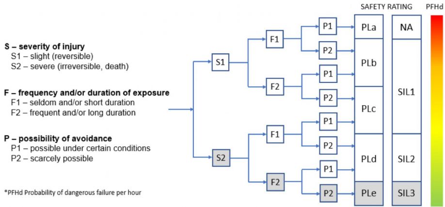
Fig. 2
Fig. 2 shows the equivalence of PL and SIL ratings. There is no SIL equivalent to PLa which is rarely applicable in motion control systems. Higher ratings (PLe and SIL3) have a lower probability of dangerous failure of the Safety Function per hour and consequently higher risk reduction. A higher PL/SIL rating places greater demands on system architecture, diagnostic coverage and Mean Time to Failure (MTTF) of system components.
Safety Functions
These are the most common Safety Functions used in motion control applications:
Safe Stopping and Holding
- STO – Safe Torque Off
- Function: disables the drive power stage so the motor can generate no torque, motor coasts to a stop if moving (SS1 normally used for stopping if available).
- Application: activated by interlock for maintenance or setup.
- Benefit: eliminates contactors to disconnect drive from motor and allows the machine power to be maintained.
- SS1 – Safe Stop 1
- Function: activates deceleration at a monitored rate then activates STO after a configurable time. Often used in conjunction with SBC (Safe Brake Control).
- Application: activated by E-Stop.
- Benefit: same as STO but also limits coasting distance which may reduce the size of safety buffer zones for large inertia loads.
- SS2 – Safe Stop 2
- Function: motor is stopped by controlled breaking then holds position via SOS.
- Application: activated by E-Stop or interlock to allow human interaction.
- Benefit: same as SS1 but position can be held without a brake. Downtime is potentially shorter due to uniterrupted closed loop control.
- SOS – Safe Operating Stop
- Function: motor holds current position within a window, falls back to STO if position is out of window, often used in conjunction with SS2,
- Application: activated by interlock to allow human interaction.
- Benefit: same as SS2.
- SBC – Safe Brake Control
- Function: supplies a safe output signal to disengage a mechanical holding brake on the motor. The brake must require a current to operate against a spring. Typically used in conjunction with STO, SS1 and SBT.
- Application: activated by E-Stop or interlock when motor is at rest to allow human interaction particularly when gravity is involved.
- Benefit: prevents damage and potential injury due to gravity.
- SBT – Safe Brake Test
- Function: performs brake operational check.
- Application: supplement to Safe Brake implementation.
- Benefit: detects wear and brake faults.
Safe Motion
- SLS – Safe Limited Speed
- Function: ensures that a predefined speed limit is not exceeded. Different limits depending on direction are possible. If the speed is exceeded a configurable response is initiated. The response is typically STO as the over-speed is most likely caused by an encoder fault.
- Application: safe speed to allow human interaction
- Benefit: higher productivity when human not present, elimination of guarding
- SLP – Safe Limited Position
- Function: ensures that predefined position limits are not exceeded. If the limits are exceeded a configurable response is initiated. The response is typically STO as the outside-limit condition is most likely caused by an encoder fault.
- Application: establishes protected zones
- Benefit: elimination of guarding and physical limit switches
- SDI – Safe Direction
- Function: ensures that motion is the predefined direction only. If the direction is wrong a configurable response, typically, STO is initiated.
- Application: allows workpieces to be removed if the machine is moving in a safe direction – away from the operator.
- Benefit: potential productivity increase and protection of machinery that should only turn in one direction.
System Implications of Safety Functions
In many systems, the drive only has STO capability. STO incorporates discrete, redundant enable inputs for the drive power stage. It is a hardware solution with no firmware involved. All other Safety Functions, which do require firmware, are handled by a Safe PLC designed to conform to safe architecture and firmware guidelines. The Safe PLC, as shown in Fig. 3, performs a monitoring function via a second encoder. If a Safety Function is triggered, the Safe PLC activates STO to disable the drive power stage.
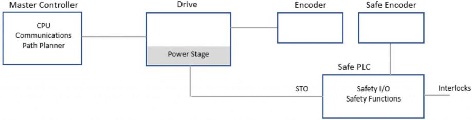
Fig. 3
The current trend is to incorporate Safety Functions in a Safe Drive connected to a Safe Encoder. This reduces system complexity and simplifies wiring. If high Safety Function ratings are required, the encoder provides redundant position information (two individual readings) as shown in Fig. 4. A safety rated protocol is employed between the encoder and drive as well as redundant communication frame monitoring in the drive. The drive and encoder become a safety system. If additional diagnostics are provided by the drive it may be possible to use a PLd/SIL2 encoder for a PLe/SIL3 Safety Function.
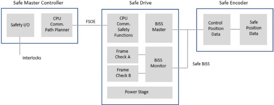
Fig. 4
STO is not connected to the drive power stage. The interlocks are connected to a Safe Controller which can command STO and other Safety Functions to multiple drives via a safety rated communication network. In Fig. 4 the safety network is EtherCAT® employing FSOE (Functional Safety Over EtherCAT®).
Conclusion
Functional Safety is a growing trend, particularly in Europe. The goal of Functional Safety is to reduce risk (remaining after design measures have been taken) to an acceptable level. For machinery in the motion control industry this is accomplished by a standard set of Safety Functions. The Safety Functions are rated by PL or SIL methodologies which consider hazard severity, frequency of exposure and possibility of avoidance. The end result can be simplified, lower cost systems, increased productivity and safer machine-human interaction without the need for bulky protective equipment.
The content & opinions in this article are the author’s and do not necessarily represent the views of RoboticsTomorrow
Comments (0)
This post does not have any comments. Be the first to leave a comment below.
Featured Product