2017 - Most Popular Article - To achieve the highest performance, the stepper motor can be treated as a 2 phase brushless servo motor. Current to the motor will then be controlled as a function of the error signal just as with standard servo motors.
Forms of Closed Loop Stepper Control
Contributed by | Galil Motion Control, Inc.
Stepper motors are employed in a variety of applications across the engineering spectrum because they are inexpensive, simple to operate, and offer high torque at low speeds. However, stepper motors suffer from drawbacks such as missed steps, decreased torque at high speeds, resonances, and high power consumption. In order to mitigate these issues, Galil has three methods of closing the loop around a stepper motor: End point correction, closed loop microstepping, and driving the stepper motor as a 2-phase brushless motor.
Stepper Motor Basics
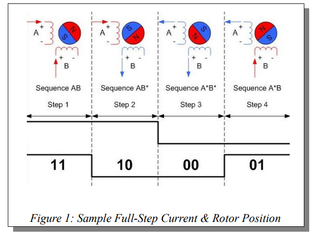
Stepper motors have multiple "toothed" electromagnets arranged around a gear-shaped rotor. To make the motor shaft turn, these electromagnets are energized in a specific sequence. Figure 1 shows a simplified view of this process for a 2-phase stepper motor. Each specific sequence corresponds to one step of the motor. A stepper motor typically has 200 steps per revolution.
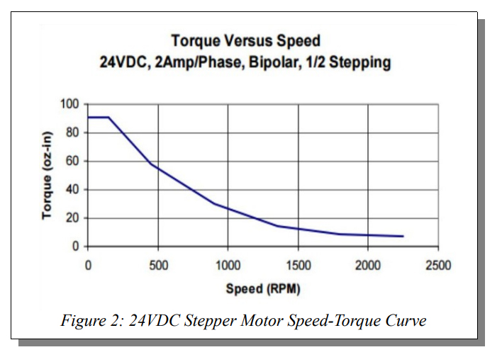
Stepper motors do not come without some drawbacks. The first drawback of a stepper motor is that it operates at full current at all times. This leads to wasted energy and excess heat generation. Second, fundamental to the operation of stepper motors is the vibration caused when they change their position in discrete steps. When the step frequency matches the natural oscillation or resonant frequency of the stepper motor the amplitude of these vibrations will increase, leading to loss of position. Stepper motors also experience a significant torque decrease as the speed of the motor increases. A common speed-torque curve is shown in Error: Reference source not found. Lastly, the positional resolution is limited by the number of steps per revolution. If increased resolution is needed, the stepper can be driven through the process of microstepping.
Microstepping
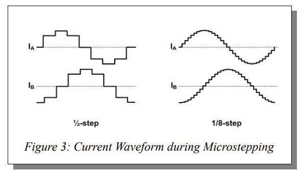
Microstepping is a method of driving a stepper motor such that every whole step of the motor is broken down into smaller increments called microsteps. Microstepping typically creates between 2 and 256 microsteps per full step which means that the 200 step per revolution motor can now have up to 51200 of these microsteps per revolution. Figure 3 details the current waveform through each stepper motor phase with an increasing number of microsteps per full step.
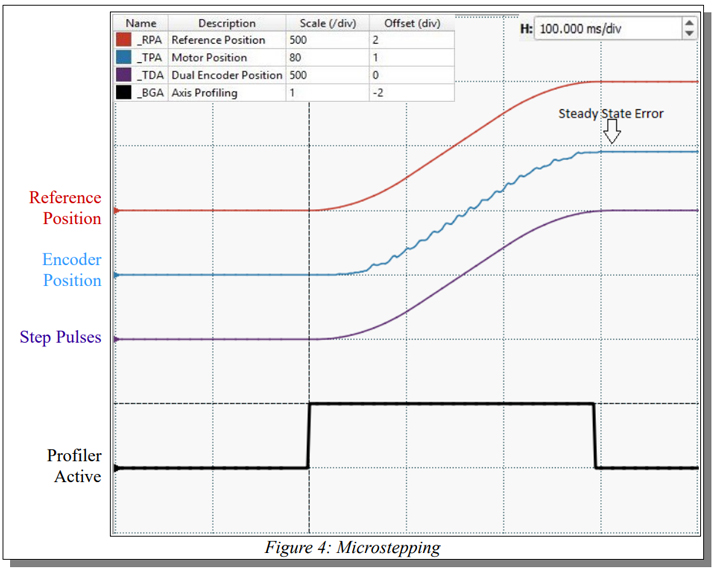
The actual accuracy of microstepping is largely dependent on external forces. Microstepping is accurate to within a full step of the motor, however if more than a half step of error is present then loss of position will occur. Motion will not occur if friction, gravity, or any other force is large enough to prevent the small change in current between two microstepping positions from affecting the position of the motor. Figure 4 shows a plot of a point to point move executed in a system driven by a stepper motor coupled with an encoder. The red line is the expected position of the stepper motor, the purple line is the step pulses output to the motor, and the blue line is the motor position measured by the encoder. The black line indicates when the controller is actively profiling motion. Due to friction in the system, the stepper motor's final position does not match the commanded position resulting in some steady state error.
End-Point Correction
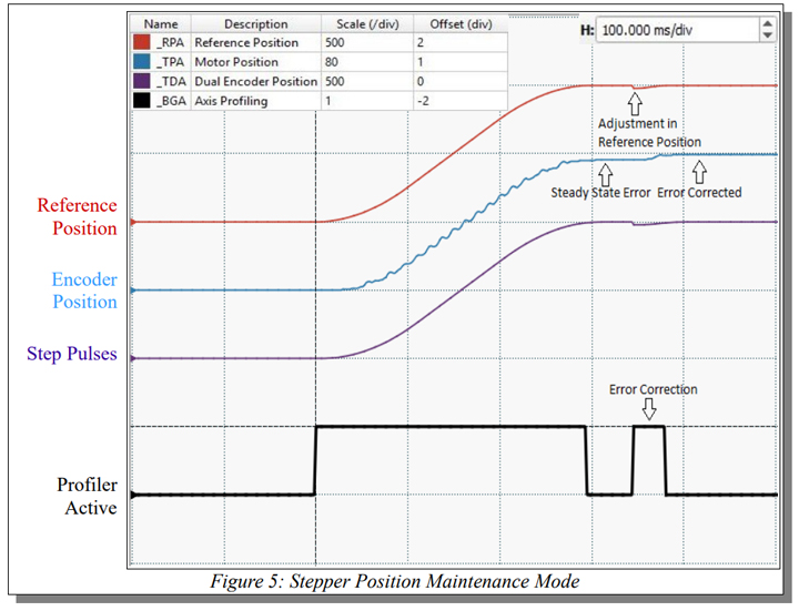
By utilizing encoder feedback to recognize this position error, the end point can be adjusted by commanding additional step pulses to bring the motor into the correct position. Galil calls this Stepper Position Maintenance mode, or SPM. SPM still operates the stepper in the microstepping mode, but the endpoint accuracy can now be verified and adjusted. This mode works by comparing the commanded position of the stepper motor to the actual position output from the encoder just before completion of a move. Figure 5 shows the same system as Figure 4 now being operated in Stepper Position Maintenance mode. After the end of the move, the position error is recognized and the reference position is adjusted to account for this error. An error correction move is then commanded to bring the stepper to the correct position. By adding the encoder, the controller now has the ability to recognize and correct for error present in the system. The same move which previously resulted in steady state error due to friction can now be accounted for and corrected.
Closed-Loop Microstepping
SPM mode is intended for applications where the only concern is end point accuracy. When it is necessary to continuously correct for error, Galil offers Closed Loop Microstepping (CLS) mode. Figure 6 shows the stepper system now being driven in CLS mode. In addition to the reference position and encoder position, an error signal (green line) is now generated internally on the controller and is used to adjust the stepper motor's position continuously. It is important to note that in CLS mode motion is now profiled based on the encoder position, but step pulses are still generated by the controller to drive the stepper motor.
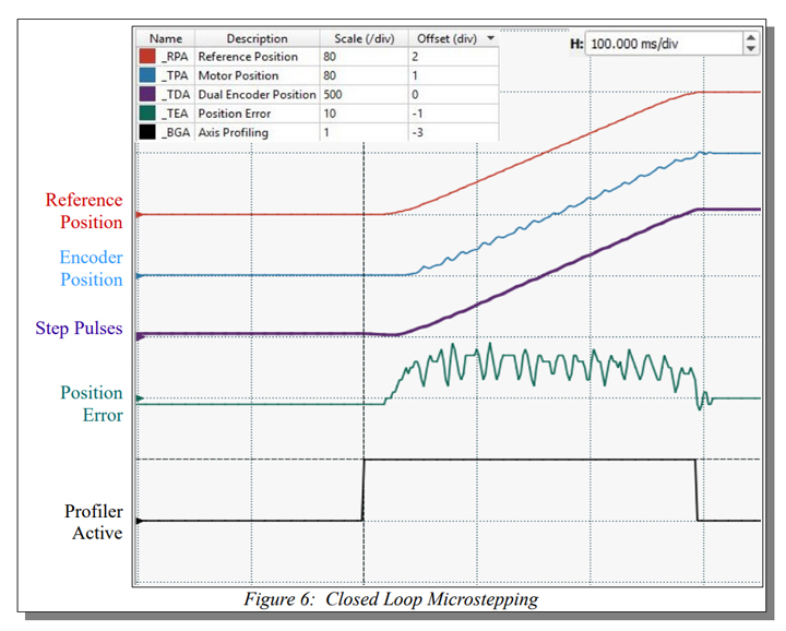
The error signal generated is fed through Galil's CLS filter which then compensates for any error present in the system by adjusting the step pulses output to the stepper. Closed Loop Microstepping is a true closed loop mode of operation, and is the optimum use of a stepper motor still being driven as a stepper. Closed loop operation brings with it the risk of instability if the loop is not correctly tuned, so care must be taken to achieve stability. Furthermore, this mode is still power inefficient and has low bandwidth when compared against a classic servo system. This low bandwidth can be made even lower when using external 3rd party stepper drives with low current loop bandwidth and non-linear characteristics.
Driving a Stepper as a 2-Phase Brushless Motor
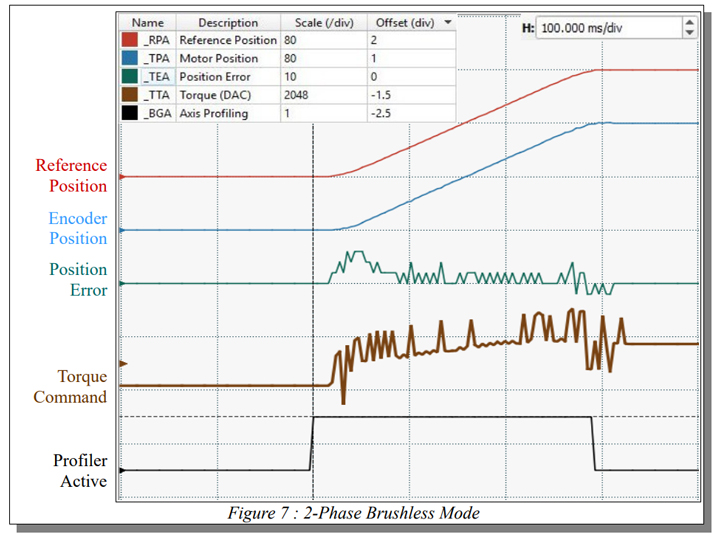
To achieve the highest performance, the stepper motor can be treated as a 2 phase brushless servo motor. Current to the motor will then be controlled as a function of the error signal just as with standard servo motors. Galil refers to as 2 Phase Brushless mode, or 2PB. Figure 7 details the stepper motor system being driven in this mode. Now, rather than step pulses, a torque command signal (brown line) is generated by the controller to be fed to one of Galil's internal amplifiers operating in 2PB mode in order to control the position of the motor. times. A stepper motor driven in 2PB mode is analogous to a classic servo motor attached to a speed reduction gearbox. Because this mode operates like a standard servo motor, the full range of Galil's advanced PID filter capabilities can be now utilized, including the notch, pole, and feedforward filters. In order to drive the stepper motor in this way, the amplifier must be made more sophisticated to properly deliver only the instantaneous required current to the motor. This results in the stepper motor running power efficiently and causes it to generate far less heat.
Closed Loop Stepper Control
By leveraging Galil's methods of closed loop stepper control, the various shortcomings of stepper motors can be overcome. The endpoint position can be adjusted for inaccuracies with stepper position maintenance mode, the position can be dynamically adjusted with closed loop microstepping, and lastly the stepper motor can be treated as a 2-phase brushless servo to further increase the performance and efficiency of the motor. If you have questions on which mode of closed loop stepper operation is appropriate for your application, contact our Applications Engineering department at (916) 626-0101 or by email at support@galil.com.
The content & opinions in this article are the author’s and do not necessarily represent the views of RoboticsTomorrow
Featured Product

